Showing posts with label ESP32. Show all posts

Wednesday, August 25, 2021

Bi-direction BLE communication between Raspberry Pi/Python (with PyQt5 GUI) and ESP32/Arduino Nano RP2040 Connect

Raspberry Pi/Python/bluepy + ESP32

With bluepy installed, this exercise implement BLE client side on Raspberry Pi using Python, connect to ESP32 BLE uart server, send and receive data in between.


Prepare ESP32 BLE_uart

ESP32 side (NodeMCU ESP-32S) is programmed in Arduino framework. 

In Arduino IDE
- Open Examples > ESP32 BLE Arduino > BLE_uart in Arduino IDE, and upload to ESP32 board.

It's a BLE setup as server, wait connection. Once connected, send data to client repeatedly and display received data to Serial Monitor.

Test with nRF Connect App 

To verify the function of ESP32 BLE_art on Android device, install nRF Connect for Mobile App by Nordic Semiconductor ASA.

Simple test Python code -

Automatically connect to BLE_uart, send and receive data repeatedly.

 ex_bluepy_uart.py

from bluepy import btle
import time

class MyDelegate(btle.DefaultDelegate):
    def __init__(self):
        btle.DefaultDelegate.__init__(self)
        # ... initialise here

    def handleNotification(self, cHandle, data):
        #print("\n- handleNotification -\n")
        print(data)
        # ... perhaps check cHandle
        # ... process 'data'

# Initialisation  -------

p = btle.Peripheral("3c:71:bf:0d:dd:6a")   #NodeMCU-32S
#p = btle.Peripheral("24:0a:c4:e8:0f:9a")   #ESP32-DevKitC V4

# Setup to turn notifications on, e.g.
svc = p.getServiceByUUID("6E400001-B5A3-F393-E0A9-E50E24DCCA9E")
ch_Tx = svc.getCharacteristics("6E400002-B5A3-F393-E0A9-E50E24DCCA9E")[0]
ch_Rx = svc.getCharacteristics("6E400003-B5A3-F393-E0A9-E50E24DCCA9E")[0]

p.setDelegate( MyDelegate())

setup_data = b"\x01\00"
p.writeCharacteristic(ch_Rx.valHandle+1, setup_data)

lasttime = time.localtime()

while True:
    """
    if p.waitForNotifications(1.0):
        pass  #continue

    print("Waiting...")
    """
    
    nowtime = time.localtime()
    if(nowtime > lasttime):
        lasttime = nowtime
        stringtime = time.strftime("%H:%M:%S", nowtime)
        btime = bytes(stringtime, 'utf-8')
        try:
            ch_Tx.write(btime, True)
        except btle.BTLEException:
            print("btle.BTLEException");
        #print(stringtime)
        #ch_Tx.write(b'wait...', True)
        
    # Perhaps do something else here
Python code with PyQt5 GUI -
- Click "Start BLE" button to connect to BLE_uart.
- Display received data on QPlainTextEdit, and send user entered data to BLE


pyqt5_bluepy_thread_.py
import sys
import time

import requests
from PyQt5.QtCore import QObject, QRunnable, QThreadPool, QTimer, pyqtSignal, pyqtSlot
from PyQt5.QtWidgets import (
    QApplication, QLabel, QMainWindow,  QPlainTextEdit, QPushButton, QVBoxLayout, QWidget,
    )

from bluepy import btle

class WorkerSignals(QObject):
    signalMsg = pyqtSignal(str)
    signalRes = pyqtSignal(str)
    
class MyDelegate(btle.DefaultDelegate):
    
    def __init__(self, sgn):
        btle.DefaultDelegate.__init__(self)
        self.sgn = sgn

    def handleNotification(self, cHandle, data):
        
        try:
            dataDecoded = data.decode()
            self.sgn.signalRes.emit(dataDecoded)
        except UnicodeError:
            print("UnicodeError: ", data)

class WorkerBLE(QRunnable):
    
    def __init__(self):
        super().__init__()
        self.signals = WorkerSignals()
        self.rqsToSend = False
        
    @pyqtSlot()
    def run(self):
        self.signals.signalMsg.emit("WorkerBLE start")
        
        #---------------------------------------------
        p = btle.Peripheral("3c:71:bf:0d:dd:6a")
        p.setDelegate( MyDelegate(self.signals) )

        svc = p.getServiceByUUID("6E400001-B5A3-F393-E0A9-E50E24DCCA9E")
        self.ch_Tx = svc.getCharacteristics("6E400002-B5A3-F393-E0A9-E50E24DCCA9E")[0]
        ch_Rx = svc.getCharacteristics("6E400003-B5A3-F393-E0A9-E50E24DCCA9E")[0]

        setup_data = b"\x01\00"
        p.writeCharacteristic(ch_Rx.valHandle+1, setup_data)

        # BLE loop --------

        while True:
            """
            if p.waitForNotifications(1.0):
                # handleNotification() was called
                continue

            print("Waiting...")
            """
            
            p.waitForNotifications(1.0)
            
            if self.rqsToSend:
                self.rqsToSend = False

                try:
                    self.ch_Tx.write(self.bytestosend, True)
                except btle.BTLEException:
                    print("btle.BTLEException");
            
        #---------------------------------------------hellohello
        self.signals.signalMsg.emit("WorkerBLE end")
        
    def toSendBLE(self, tosend):
        self.bytestosend = bytes(tosend, 'utf-8')
        self.rqsToSend = True
        """
        try:
            self.ch_Tx.write(bytestosend, True)
        except BTLEException:
            print("BTLEException");
        """
            
class MainWindow(QMainWindow):
    
    def __init__(self):
        super().__init__()
        
        layout = QVBoxLayout()
        
        buttonStartBLE = QPushButton("Start BLE")
        buttonStartBLE.pressed.connect(self.startBLE)
        
        self.console = QPlainTextEdit()
        self.console.setReadOnly(True)
        
        self.outconsole = QPlainTextEdit()
        
        buttonSendBLE = QPushButton("Send message")
        buttonSendBLE.pressed.connect(self.sendBLE)

        layout.addWidget(buttonStartBLE)
        layout.addWidget(self.console)
        layout.addWidget(self.outconsole)
        layout.addWidget(buttonSendBLE)
        
        w = QWidget()
        w.setLayout(layout)
        
        self.setCentralWidget(w)
        
        self.show()
        self.threadpool = QThreadPool()
        print(
            "Multithreading with Maximum %d threads" % self.threadpool.maxThreadCount())
            
    def startBLE(self):
        self.workerBLE = WorkerBLE()
        self.workerBLE.signals.signalMsg.connect(self.slotMsg)
        self.workerBLE.signals.signalRes.connect(self.slotRes)
        self.threadpool.start(self.workerBLE)
        
    def sendBLE(self):
        strToSend = self.outconsole.toPlainText()
        self.workerBLE.toSendBLE(strToSend)
        
    def slotMsg(self, msg):
        print(msg)
        
    def slotRes(self, res):
        self.console.appendPlainText(res)
        
app = QApplication(sys.argv)
window = MainWindow()
app.exec()


Raspberry Pi/Python/bluepy + Arduino Nano RP2040 Connect

Now, replace ESP32 with Arduino Nano RP2040 Connect, running following code using ArduinoBLE library. Please  note that you have to modify Python code to match with Arduino Nano RP2040 Connect's MAC address.


BLE_peripheral_uart.ino
/*
 * BLE_peripheral_uart:
 * modifid from Examples > ArduinoBLE > Peripheral > CallbackLED
 * 
 * Bi-direction BLE communication between Raspberry Pi/Python (with PyQt5 GUI) 
 * and ESP32/Arduino Naon RP2040 Connect
 * http://helloraspberrypi.blogspot.com/2021/08/bi-direction-ble-communication-between.html
 * 
*/

#include <ArduinoBLE.h>

#define SERVICE_UUID           "6E400001-B5A3-F393-E0A9-E50E24DCCA9E" // UART service UUID
#define CHARACTERISTIC_UUID_RX "6E400002-B5A3-F393-E0A9-E50E24DCCA9E"
#define CHARACTERISTIC_UUID_TX "6E400003-B5A3-F393-E0A9-E50E24DCCA9E"

//BLEService ledService("19B10000-E8F2-537E-4F6C-D104768A1214"); // create service
BLEService uartService(SERVICE_UUID); // create service

// create switch characteristic and allow remote device to read and write
//BLEByteCharacteristic switchCharacteristic("19B10001-E8F2-537E-4F6C-D104768A1214", BLERead | BLEWrite);

BLEStringCharacteristic rxCharacteristic(CHARACTERISTIC_UUID_RX, BLEWrite, 30);
BLEStringCharacteristic txCharacteristic(CHARACTERISTIC_UUID_TX, BLENotify, 30);

// const int ledPin = LED_BUILTIN; // pin to use for the LED

void setup() {
  Serial.begin(115200);
  while (!Serial);
  
  // pinMode(ledPin, OUTPUT); // use the LED pin as an output

  // begin initialization
  if (!BLE.begin()) {
    Serial.println("starting BLE failed!");

    while (1);
  }
  
  // set the local name peripheral advertises
  BLE.setLocalName("BLE_peripheral_uart");
  // set the UUID for the service this peripheral advertises
  BLE.setAdvertisedService(uartService);

  // add the characteristic to the service
  uartService.addCharacteristic(rxCharacteristic);
  uartService.addCharacteristic(txCharacteristic);

  // add service
  BLE.addService(uartService);

  // assign event handlers for connected, disconnected to peripheral
  BLE.setEventHandler(BLEConnected, blePeripheralConnectHandler);
  BLE.setEventHandler(BLEDisconnected, blePeripheralDisconnectHandler);

  // assign event handlers for characteristic
  rxCharacteristic.setEventHandler(BLEWritten, rxCharacteristicWritten);
  // set an initial value for the characteristic
  rxCharacteristic.setValue("BLE_peripheral_uart");

  // start advertising
  BLE.advertise();

  Serial.println(("Bluetooth device active, waiting for connections..."));
  Serial.println(BLE.address());
}

void loop() {
  // poll for BLE events
  BLE.poll();
}

void blePeripheralConnectHandler(BLEDevice central) {
  // central connected event handler
  Serial.print("Connected event, central: ");
  Serial.println(central.address());
}

void blePeripheralDisconnectHandler(BLEDevice central) {
  // central disconnected event handler
  Serial.print("Disconnected event, central: ");
  Serial.println(central.address());
}

void rxCharacteristicWritten(BLEDevice central, BLECharacteristic characteristic) {
  // central wrote new value to characteristic, update LED
  Serial.print("Characteristic event, written: ");

  Serial.println("len=" + 
                  String(rxCharacteristic.valueLength()));
  String valString = rxCharacteristic.value();
  Serial.println(valString);
  valString.toUpperCase();
  Serial.println(valString);
  txCharacteristic.setValue(valString);
}


Sunday, May 16, 2021

Raspberry Pi Pico/CircuitPython + ESP32/adafruit nina-fw (act as WiFi/BLE Co-Processor)

adafruit nina-fw is a slight variant of the Arduino WiFiNINA core. ESP32 with nina-fw flashed, can be used as WiFi/BLE Co-Processor. This post show how to connected ESP32 to Raspberry Pi Pico, flash ESP32 firmware using Pico, and test WiFi/BLE with Pico/CircuitPython; on Raspberry Pi.

The ESP32 used here is a ESP32-S breadout board, flash with current latest version NINA_W102-1.7.3.bin.

Connection:

	ESP32	RPi Pico
	-----	--------
3.3V	3.3V	3.3V
GND	GND	GND
SCK	IO18	GP10
MISO	IO23	GP12
MOSI	IO14	GP11
CS	IO5	GP13
BUSY	IO33	GP14
RESET	EN	GP16
GPIO0	IO0	GP9
RX	RXD0	GP0 (tx)
TX	TXD0	GP1 (rx)

Install nina-fw on ESP32 using Raspberry Pi Pico:

In my practice , Raspberry Pi Pico act as a bridge to program ESP32. esptool is used to flash ESP32, read Install esptool on Raspberry Pi OS.

Visit https://github.com/adafruit/nina-fw/releases/latest, to download latest nina-fw.bin file, NINA_W102-1.7.3.bin currently.


- Download Pico-RP2040-Passthru.UF2
- Power up Pico in Bootloader mode
- Copy Pico-RP2040-Passthru.UF2 to Pico

- Disconnect and connect Pico again. Pico now act as a passthru bridge.
- Run the command to flash nina-fw to ESP32:

$ esptool.py --port /dev/ttyACM0 --before no_reset --baud 115200 write_flash 0 NINA_W102-1.7.3.bin

where:
- /dev/ttyACM0 is the usb port connect to Pico
- NINA_W102-1.7.3.bin is the downloaded nina-fw file.

Install CircuitPython firmware on Raspberry Pi Pico again

Download libraries:

Visit https://circuitpython.org/libraries to download the appropriate bundle for your version of CircuitPython.

Unzip the file and copy adafruit_airlift, adafruit_ble, adafruit_esp32spi folder and adafruit_requests.mpy to lib folder of Pico's CIRCUITPY driver.


Test CircuitPython code on Raspberry Pi Pico:

cpyPico_ESP32_WiFi.py

import board
import busio
from digitalio import DigitalInOut

from adafruit_esp32spi import adafruit_esp32spi
import adafruit_requests as requests

print("Raspberry Pi RP2040 - ESP32SPI hardware test")

esp32_cs = DigitalInOut(board.GP13)
esp32_ready = DigitalInOut(board.GP14)
esp32_reset = DigitalInOut(board.GP16)

spi = busio.SPI(board.GP10, board.GP11, board.GP12)
esp = adafruit_esp32spi.ESP_SPIcontrol(spi, esp32_cs, esp32_ready, esp32_reset)

if esp.status == adafruit_esp32spi.WL_IDLE_STATUS:
    print("ESP32 found and in idle mode")
print("Firmware vers.", esp.firmware_version)
print("MAC addr:", [hex(i) for i in esp.MAC_address])

for ap in esp.scan_networks():
    print("\t%s\t\tRSSI: %d" % (str(ap['ssid'], 'utf-8'), ap['rssi']))

print("Done!")

ref:
Quickstart IoT - Raspberry Pi Pico RP2040 with WiFi

cpyPico_ESP32_BLE.py

import board
from adafruit_ble import BLERadio
from adafruit_ble.advertising.standard import ProvideServicesAdvertisement
from adafruit_ble.services.nordic import UARTService
from adafruit_airlift.esp32 import ESP32

esp32 = ESP32(
    reset=board.GP16,
    gpio0=board.GP9,
    busy=board.GP14,
    chip_select=board.GP13,
    tx=board.GP0,     #connect to ESP32 RX
    rx=board.GP1,     #connect to ESP32 TX
)


adapter = esp32.start_bluetooth()

ble = BLERadio(adapter)
uart = UARTService()
advertisement = ProvideServicesAdvertisement(uart)

while True:
    ble.start_advertising(advertisement)
    print("waiting to connect")
    while not ble.connected:
        pass
    print("connected: trying to read input")
    while ble.connected:
        # Returns b'' if nothing was read.
        one_byte = uart.read(1)
        if one_byte:
            print(one_byte)
            uart.write(one_byte)

ref:
Quickstart - Raspberry Pi RP2040 with BLE and CircuitPython

Tested with:
~ ESP32 running arduino-esp32 framework BLE UART Client


Wednesday, May 12, 2021

Raspberry Pi Pico/CircuitPython + ESP32/adafruit nina-fw (as WiFi Co-Processor)

Updated:
It's another post using Raspberry Pi Pico as pass through bridge to program ESP32 with nina-fw.

This post show how ESP32 flashed with adafruit nina-fw, act as WiFi Co-Processor work with Raspberry  Pi Pico with CircuitPython.

adafruit nina-fw is a slight variant of the Arduino WiFiNINA core. The ESP32 used here is a ESP32-S breadout board, flash with current latest version NINA_W102-1.7.3.bin.

Raspberry Pi Pico is flashed CircuitPython 6.2.0, with adafruit_esp32spi and adafruit_requests libraries installed.

Install nina-fw on ESP32

In my practice, esptool is used to flash ESP32, on Raspberry Pi. Read Install esptool on Raspberry Pi OS.

Download adafruit nina-fw:

Visit https://github.com/adafruit/nina-fw/releases/latest, to download latest nina-fw.bin file, NINA_W102-1.7.3.bin currently.

Flash ESP32 using esptool:

Depends on your ESP32 board, connect and force it into bootloader mode, may be:
- Press and hold GPIO0 to GND
- Reset ESP32
- Release GPIO0

Run the command:

$ esptool.py --port /dev/ttyUSB0 --before no_reset --baud 115200 write_flash 0 NINA_W102-1.7.3.bin

where:
- /dev/ttyUSB0 is the usb port connect to ESP32
- NINA_W102-1.7.3.bin is the downloaded nina-fw file.

Connect ESP32 to Raspberry Pi Pico

		ESP32		RPi Pico
3.3V		3.3V		3.3V
GND		GND		GND
SCK		IO18		GP10
MISO		IO23		GP12
MOSI		IO14		GP11
CS		IO5		GP13
BUSY		IO33		GP14
RESET		EN		GP15
GPIO0		IO0
RXD		RXD0		
TX		TXD0

Download libraries:

Visit https://circuitpython.org/libraries to download the appropriate bundle for your version of CircuitPython.


Unzip the file and copy adafruit_esp32spi folder and adafruit_requests.mpy to lib folder of Pico's CIRCUITPY driver.


Test CircuitPython code on Raspberry Pi Pico

Copy from https://learn.adafruit.com/quickstart-rp2040-pico-with-wifi-and-circuitpython/circuitpython-wifi.


import board
import busio
from digitalio import DigitalInOut

from adafruit_esp32spi import adafruit_esp32spi
import adafruit_requests as requests

print("Raspberry Pi RP2040 - ESP32SPI hardware test")

esp32_cs = DigitalInOut(board.GP13)
esp32_ready = DigitalInOut(board.GP14)
esp32_reset = DigitalInOut(board.GP15)

spi = busio.SPI(board.GP10, board.GP11, board.GP12)
esp = adafruit_esp32spi.ESP_SPIcontrol(spi, esp32_cs, esp32_ready, esp32_reset)

if esp.status == adafruit_esp32spi.WL_IDLE_STATUS:
    print("ESP32 found and in idle mode")
print("Firmware vers.", esp.firmware_version)
print("MAC addr:", [hex(i) for i in esp.MAC_address])

for ap in esp.scan_networks():
    print("\t%s\t\tRSSI: %d" % (str(ap['ssid'], 'utf-8'), ap['rssi']))

print("Done!")


reference:
adafruit learn: Quickstart IoT - Raspberry Pi Pico RP2040 with WiFi
~ adafruit_esp32spi doc
adafruit_requests doc


Thursday, April 8, 2021

ESP32/MicroPython server + Raspberry Pi/Python client, transmit image via WiFi TCP socket.

In this exercise, ESP32 (ESP32-DevKitC V4)/MicroPython play the role of AP, act as socket server. Raspberry Pi connect to ESP32 WiFi network, run Python code to load image, act as client and transmit the image to ESP32 server. The ESP32 server display the image on a 240*240 IPS (ST7789 SPI) LCD. It's is role reversed version of my previous exercise "Raspberry Pi/Python Server send image to ESP32/MicroPython Client via WiFi TCP socket".


protocol:

Client			|	    |	Server
(Raspberry Pi/Python)	|	    |	(ESP32/MicroPython)
			|	    |
			|	    |	Reset
			|           |	Setup AP
			|	    |	Setup socket server
(connect to ESP32 WiFi)	|	    |
			|	    |
connect to ESP32 server	|	    |	accepted
			|<-- ACK ---|	
send the 0th line	|---------->|	display the 0th line
			|<-- ACK ---|	send ACK
send the 1st line	|---------->|	display the 1st line
			|<-- ACK ---|	send ACK
			    .
			    .
			    .
send the 239th line	|---------->|	display the 239th line
			|<-- ACK ---|	send ACK
close socket		|           |	close socket
			|	    |
	
Server side:
(ESP32/MicroPython)

The ESP32 used is a ESP32-DevKitC V4, display is a 240*240 IPS (ST7789 SPI) LCD. Library setup and connection, refer to former post "ESP32 (ESP32-DevKitC V4)/MicroPython + 240*240 IPS (ST7789 SPI) using russhughes/st7789py_mpy lib".

upyESP32_ImgServer_AP_20210408a.py, MicroPython code run on ESP32. Save to ESP32 named main.py, such that it can run on power-up without host connected.
from os import uname
from sys import implementation
import machine
import network
import socket
import ubinascii
import utime
import st7789py as st7789
from fonts import vga1_16x32 as font
import ustruct as struct
"""
ST7789 Display  ESP32-DevKitC (SPI2)
SCL             GPIO18
SDA             GPIO23
                GPIO19  (miso not used)

ST7789_rst      GPIO5
ST7789_dc       GPIO4
"""
#ST7789 use SPI(2)

st7789_res = 5
st7789_dc  = 4
pin_st7789_res = machine.Pin(st7789_res, machine.Pin.OUT)
pin_st7789_dc = machine.Pin(st7789_dc, machine.Pin.OUT)

disp_width = 240
disp_height = 240

ssid = "ssid"
AP_ssid  = "ESP32"
password = "password"

serverIP = '192.168.1.30'
serverPort = 80

print(implementation.name)
print(uname()[3])
print(uname()[4])
print()

#spi2 = machine.SPI(2, baudrate=40000000, polarity=1)
pin_spi2_sck = machine.Pin(18, machine.Pin.OUT)
pin_spi2_mosi = machine.Pin(23, machine.Pin.OUT)
pin_spi2_miso = machine.Pin(19, machine.Pin.IN)
spi2 = machine.SPI(2, sck=pin_spi2_sck, mosi=pin_spi2_mosi, miso=pin_spi2_miso,
                   baudrate=40000000, polarity=1)
print(spi2)
display = st7789.ST7789(spi2, disp_width, disp_width,
                          reset=pin_st7789_res,
                          dc=pin_st7789_dc,
                          xstart=0, ystart=0, rotation=0)
display.fill(st7789.BLACK)

mac = ubinascii.hexlify(network.WLAN().config('mac'),':').decode()
print("MAC: " + mac)
print()

#init ESP32 as STA
wlan = network.WLAN(network.STA_IF)
wlan.active(True)
wlan.disconnect()
utime.sleep(1)

def do_connect():
    global wlan
    print('connect to network...')
    display.fill(st7789.BLACK)
    display.text(font, "connect...", 10, 10)
    
    wlan.active(True)
    if not wlan.isconnected():
        print('...')
        wlan.connect(ssid, password)
        while not wlan.isconnected():
            pass
    
    print()
    print('network config:')
    print("interface's IP/netmask/gw/DNS addresses")
    #print(wlan.ifconfig())
    myIP = wlan.ifconfig()[0]
    print(myIP)
    
    display.fill(st7789.BLACK)
    display.text(font, myIP, 10, 10)
    
def do_setupAP():
    global wlan
    print('setup AP...')
    display.fill(st7789.BLACK)
    display.text(font, "setup AP...", 10, 10)
    utime.sleep(1)
        
    ap = network.WLAN(network.AP_IF)
    ap.active(True)
    ap.config(essid=AP_ssid, password=password)

    while ap.active() == False:
      pass
    
    print(ap.active())
    print()
    print('network config:')
    myIP = ap.ifconfig()
    print(myIP)
    
    display.fill(st7789.BLACK)
    display.text(font, myIP[0], 10, 10)

def do_setupServer():
    global wlan
    global display
    
    addr = socket.getaddrinfo('0.0.0.0', serverPort)[0][-1]
    s = socket.socket()
    s.bind(addr)
    s.listen(1)
    
    print('listening on', addr)
    display.text(font, ':'+str(serverPort), 10, 50)
    
    while True:
        print('waiting connection...')
        cl, addr = s.accept()
        cl.settimeout(5)
        print('client connected from:', addr)
        
        display.fill(st7789.BLACK)
        display.text(font, addr[0], 10, 10)
    
        cl.sendall('ACK')
        print('Firt ACK sent')
        
        display.set_window(0, 0, disp_width-1, disp_height-1)
        pin_st7789_dc.on()
        for j in range(disp_height):
            
            try:
                buff = cl.recv(disp_width*3)
                #print('recv ok: ' + str(j))
            except:
                print('except: ' + str(j))
            
            for i in range(disp_width):
                offset= i*3
                spi2.write(struct.pack(st7789._ENCODE_PIXEL,
                                       (buff[offset] & 0xf8) << 8 |
                                       (buff[offset+1] & 0xfc) << 3 |
                                       buff[offset+2] >> 3))
            #print('send ACK : ' + str(j))
            cl.sendall(bytes("ACK","utf-8"))
            #print('ACK -> : ' + str(j))
        utime.sleep(1)
        cl.close()
    print('socket closed')
    
#do_connect()
do_setupAP()

try:
    do_setupServer()
except:
    print('error')
    display.text(font, "Error", 10, 200)
finally:
    print('wlan.disconnect()')
    wlan.disconnect()
    
print('\n- bye -')
Client Side:
(Raspberry Pi/Python)

Connect Raspberry Pi to ESP32 WiFi network before run the Python code.

Load and send images with fixed resolution 240x240 (match with the display in client side) to server. My former post "min. version of RPi/Python Code to control Camera Module with preview on local HDMI" is prepared for this purpose to capture using Raspberry Pi Camera Module .

pyqTCP_ImgClient_20210408a.py
import sys
from pkg_resources import require
import time
import matplotlib.image as mpimg
import socket

#HOST = '192.168.1.34'   # The server's hostname or IP address
HOST = '192.168.4.1'
PORT = 80               # The port used by the server

from PyQt5.QtWidgets import (QApplication, QWidget, QPushButton, QLabel,
                             QFileDialog, QHBoxLayout, QVBoxLayout)
from PyQt5.QtGui import QPixmap, QImage

print(sys.version)

class AppWindow(QWidget):

    camPreviewState = False  #not in Preview
    fileToUpload = ""

    def __init__(self):
        super().__init__()

        lbSysInfo = QLabel('Python:\n' + sys.version)
        vboxInfo = QVBoxLayout()
        vboxInfo.addWidget(lbSysInfo)

        #setup UI

        btnOpenFile = QPushButton("Open File", self)
        btnOpenFile.clicked.connect(self.evBtnOpenFileClicked)
        self.btnUpload = QPushButton("Upload", self)
        self.btnUpload.clicked.connect(self.evBtnUploadClicked)
        self.btnUpload.setEnabled(False)

        vboxCamControl = QVBoxLayout()
        vboxCamControl.addWidget(btnOpenFile)
        vboxCamControl.addWidget(self.btnUpload)
        vboxCamControl.addStretch()

        self.lbImg = QLabel(self)
        self.lbImg.resize(240, 240)
        self.lbImg.setStyleSheet("border: 1px solid black;")

        hboxCam = QHBoxLayout()
        hboxCam.addWidget(self.lbImg)
        hboxCam.addLayout(vboxCamControl)

        self.lbPath = QLabel(self)

        vboxMain = QVBoxLayout()
        vboxMain.addLayout(vboxInfo)
        vboxMain.addLayout(hboxCam)
        vboxMain.addWidget(self.lbPath)
        vboxMain.addStretch()
        self.setLayout(vboxMain)

        self.setGeometry(100, 100, 500,400)
        self.show()

    #wait client response in 3 byte len
    def wait_RESP(self, sock):
        #sock.settimeout(10)
        res = str()
        data = sock.recv(4)
        return data.decode("utf-8")

    def sendImageToServer(self, imgFile):
        print(imgFile)
        imgArray = mpimg.imread(imgFile)

        with socket.socket(socket.AF_INET, socket.SOCK_STREAM) as s:
            s.connect((HOST, PORT))
            print(self.wait_RESP(s))

            for j in range(240):
                time.sleep(0.1)
                b = bytes(imgArray[j])

                #print('send img : ' + str(j))
                s.sendall(bytes(b))
                #print('img sent : ' + str(j))

                ans = self.wait_RESP(s)
                #print(ans + " : " + str(j))

            print('image sent finished')
            s.close()

    def evBtnUploadClicked(self):
        print("evBtnUploadClicked()")
        print(self.fileToUpload)
        self.sendImageToServer(self.fileToUpload)

    def evBtnOpenFileClicked(self):
        options = QFileDialog.Options()
        options |= QFileDialog.DontUseNativeDialog
        targetPath, _ = QFileDialog.getOpenFileName(
            self, 'Open file', '/home/pi/Desktop',
            'Image files (*.jpg)', options=options)

        if targetPath:
            print(targetPath)
            self.lbPath.setText(targetPath)

            with open(targetPath):
                pixmap = QPixmap(targetPath)

                #accept 240x240 image only
                if pixmap.width()==240 and pixmap.height()==240:
                    self.lbImg.setPixmap(pixmap)
                    self.btnUpload.setEnabled(True)
                    self.fileToUpload = targetPath
                else:
                    self.btnUpload.setEnabled(False)


    def evBtnOpenFileClickedX(self):

        targetPath="/home/pi/Desktop/image.jpg"

        print(targetPath)
        self.lbPath.setText(targetPath)

        try:
            with open(targetPath):
                pixmap = QPixmap(targetPath)
                self.lbImg.setPixmap(pixmap)

                #as a exercise, get some info from pixmap
                print('\npixmap:')
                print(pixmap)
                print(type(pixmap))
                print(str(pixmap.width()) + " : " + str(pixmap.height()))
                print()

                print('convert to Image')
                qim = pixmap.toImage()
                print(qim)
                print(type(qim))
                print()

                print('read a pixel from image')
                qrgb = qim.pixel(0, 0)
                print(hex(qrgb))
                print(type(qrgb))

                r, g, b = qRed(qrgb), qGreen(qrgb), qBlue(qrgb)
                print([hex(r), hex(g), hex(b)])
                print()

        except FileNotFoundError:
            print('File Not Found Error')

if __name__ == '__main__':
    print('run __main__')
    app = QApplication(sys.argv)
    window = AppWindow()
    sys.exit(app.exec_())

print("- bye -")
Remark:
At beginning, I tried to set ESP32 as STA, by calling do_connect(), connect to my home/mobile WiFi network. But the result is very unstable in: Pi client send 240 pixel but ESP32 server can't receive all. That's why you can find some commented debug code (using print()) in the program.

After then, set ESP32 as AP, Pi connect to ESP32 WiFi network. The result have great improved and very stable.


Wednesday, March 24, 2021

Raspberry Pi/Python Server send image to ESP32/MicroPython Client via WiFi TCP socket


In this exercise, Raspberry Pi/Python3 act as socket server, ESP32/MicroPython act as client connect to server via WiFi TCP. Once received, server (Pi/Python) send a image (240x240) to client (ESP32/MicroPython), then the client display the image on a 240*240 IPS (ST7789 SPI) LCD.


To make it more flexible, the image is in 240 batch of 240 pixel x 3 color (r, g, b).

protocol:

Server			|	    |	Client
(Raspberry Pi/Python)	|	    |	(ESP32/MicroPython)
			|	    |
Start			|	    |	Reset
			|	    |
Setup as 		|	    |
socketserver.TCPServer	|	    |
			|	    |
			|	    |	Join the WiFi network
		        |	    |	Connect to server with socket
			|	    |	
			|<-- ACK ---|	send ACK
send the 0th line	|---------->|	display the 0th line
			|<-- ACK ---|	send ACK
send the 1st line	|---------->|	display the 1st line
			    .
			    .
			    .
send the 239th line	|---------->|	display the 239th line
			|<-- ACK ---|	send ACK
close socket		|	    |	close socket
			|	    |
wait next		|	    |	bye	


Client side:

(ESP32/MicroPython)

The ESP32 used is a ESP32-DevKitC V4, display is a 240*240 IPS (ST7789 SPI) LCD. Library setup and connection, refer to former post "ESP32 (ESP32-DevKitC V4)/MicroPython + 240*240 IPS (ST7789 SPI) using russhughes/st7789py_mpy lib".

upyESP32_ImgClient_20210324c.py, MicroPython code run on ESP32. Modify ssid/password and serverIP for your WiFi network.
from os import uname
from sys import implementation
import machine
import network
import socket
import ubinascii
import utime
import st7789py as st7789
from fonts import vga1_16x32 as font
import ustruct as struct
"""
ST7789 Display  ESP32-DevKitC (SPI2)
SCL             GPIO18
SDA             GPIO23
                GPIO19  (miso not used)

ST7789_rst      GPIO5
ST7789_dc       GPIO4
"""
#ST7789 use SPI(2)

st7789_res = 5
st7789_dc  = 4
pin_st7789_res = machine.Pin(st7789_res, machine.Pin.OUT)
pin_st7789_dc = machine.Pin(st7789_dc, machine.Pin.OUT)

disp_width = 240
disp_height = 240

ssid = "your ssid"
password = "your password"

serverIP = '192.168.1.30'
serverPort = 9999

print(implementation.name)
print(uname()[3])
print(uname()[4])
print()

spi2 = machine.SPI(2, baudrate=40000000, polarity=1)
print(spi2)
display = st7789.ST7789(spi2, disp_width, disp_width,
                          reset=pin_st7789_res,
                          dc=pin_st7789_dc,
                          xstart=0, ystart=0, rotation=0)
display.fill(st7789.BLACK)

mac = ubinascii.hexlify(network.WLAN().config('mac'),':').decode()
print("MAC: " + mac)
print()

#init ESP32 as STA
wlan = network.WLAN(network.STA_IF)
wlan.active(True)
wlan.disconnect()
utime.sleep(1)

def do_connect():
    global wlan
    print('connect to network...')
    display.fill(st7789.BLACK)
    display.text(font, "connect...", 10, 10)
    
    wlan.active(True)
    if not wlan.isconnected():
        print('...')
        wlan.connect(ssid, password)
        while not wlan.isconnected():
            pass
    
    print()
    print('network config:')
    print("interface's IP/netmask/gw/DNS addresses")
    print(wlan.ifconfig())
    
    display.fill(st7789.BLACK)
    display.text(font, "connected", 10, 10)
    
def do_scan():
    global wlan
    print('scan network...')
    wlan.active(True)
    for network in wlan.scan():
        print(network)
        
def do_connectServer():
    global wlan
    global display
    
    addr = socket.getaddrinfo(serverIP, serverPort)[0][-1]
    print(addr)
    s = socket.socket()
    s.connect(addr)
    
    print('---')
    display.fill(st7789.BLACK)
    display.text(font, "waiting...", 10, 10)

    print('Send ACK')
    s.sendall(bytes("ACK","utf-8"))
        
    display.set_window(0, 0, disp_width-1, disp_height-1)
    pin_st7789_dc.on()
    for j in range(disp_height):
        
        buff = s.recv(disp_width*3)
        for i in range(disp_width):
            offset= i*3
            spi2.write(struct.pack(st7789._ENCODE_PIXEL,
                                   (buff[offset] & 0xf8) << 8 |
                                   (buff[offset+1] & 0xfc) << 3 |
                                   buff[offset+2] >> 3))
            
        s.sendall(bytes("ACK","utf-8"))

    s.close()
    print('socket closed')
    
do_connect()
try:
    do_connectServer()
except:
    print('error')
    display.text(font, "Error", 10, 200)
finally:
    print('wlan.disconnect()')
    wlan.disconnect()
    
print('\n- bye -')

Server Side:
(Raspberry Pi/Python)

The server will send Desktop/image.jpg with fixed resolution 240x240 (match with the display in client side). My former post "min. version of RPi/Python Code to control Camera Module with preview on local HDMI" is prepared for this purpose to capture using Raspberry Pi Camera Module .

pyMyTCP_ImgServer_20210324c.py, Python3 code run on Raspberry Pi.
import socketserver
import platform
import matplotlib.image as mpimg

imageFile = '/home/pi/Desktop/image.jpg'

print("sys info:")
for info in platform.uname():
    print(info)

class MyTCPHandler(socketserver.BaseRequestHandler):

    #wait client response in 3 byte len
    def wait_RESPONSE(self, client):
        client.settimeout(10)
        res = str()
        data = client.recv(4)
        return data.decode("utf-8")

    def handle(self):
        msocket = self.request

        print("{} connected:".format(self.client_address[0]))
        imgArray = mpimg.imread(imageFile)

        self.wait_RESPONSE(msocket)     #dummy assume 'ACK' received
        print('first RESPONSE received')

        for j in range(240):
            b = bytes(imgArray[j])
            msocket.sendall(bytes(b))
            self.wait_RESPONSE(msocket)  #dummy assume 'ACK' received

        print('image sent finished')

        msocket.close()


if __name__ == "__main__":
    HOST, PORT = "localhost", 9999

    # Create the server, binding to localhost on port 9999
    #with socketserver.TCPServer((HOST, PORT), MyTCPHandler) as server:
    with socketserver.TCPServer(('', PORT), MyTCPHandler) as server:
        # Activate the server; this will keep running until you
        # interrupt the program with Ctrl-C

        server.serve_forever()
This socketserver.TCPServer((HOST, PORT), MyTCPHandler) as server example is modify from Python 3 socketserver.TCPServer Example. I assume socketserver.TCPServer will handle Ctrl-C with port close. But in my test, SOMETIMES throw OSError of "Address already in use". In my practice, try pressing Ctrl-C in REPL/restart repeatedly.


Next:

Saturday, March 20, 2021

ESP32 (ESP32-DevKitC V4)/MicroPython + 240*240 IPS (ST7789 SPI) using russhughes/st7789py_mpy lib

To display with 240*240 IPS (ST7789 SPI) LCD on ESP32 (ESP32-DevKitC V4)/MicroPython using russhughes/st7789py_mpy lib.

Connection:

In my exercise, SPI2 is used to send command to ST7789.

ST7789		ESP32-DevKitC
GND		GND
VCC		3V3
SCL		GPIO18
SDA		GPIO23
RES		GPIO5
DC		GPIO4
BLK		3V3


Install library:

Visit https://github.com/russhughes/st7789py_mpy, download lib/st7789py.py, save to ESP32.

In my test, have to edit st7789py.py littlle bit, otherwise it will be reported with error:
AttributeError: 'ST7789' object has no attribute 'xstart'

Edit st7789py.py, to add the line under  def __init__():
	self.xstart = xstart
	self.ystart = ystart

Download fonts/vga1_16x32.py (or any font files you want) to ESP32 under new directory "fonts".

Example code:

upyESP32_st7789.py
"""
ESP32-DevKitC V4/MicroPython exercise
240x240 ST7789 SPI LCD
using MicroPython library:
https://github.com/russhughes/st7789py_mpy

"""

import uos
import machine
import st7789py as st7789
from fonts import vga1_16x32 as font
import random
import ustruct as struct
import utime

"""
ST7789 Display  ESP32-DevKitC (SPI2)
SCL             GPIO18
SDA             GPIO23
                GPIO19  (miso not used)

ST7789_rst      GPIO5
ST7789_dc       GPIO4
"""
#ST7789 use SPI(2)

st7789_res = 5
st7789_dc  = 4
pin_st7789_res = machine.Pin(st7789_res, machine.Pin.OUT)
pin_st7789_dc = machine.Pin(st7789_dc, machine.Pin.OUT)

disp_width = 240
disp_height = 240
CENTER_Y = int(disp_width/2)
CENTER_X = int(disp_height/2)

print(uos.uname())
spi2 = machine.SPI(2, baudrate=40000000, polarity=1)
print(spi2)
display = st7789.ST7789(spi2, disp_width, disp_width,
                          reset=pin_st7789_res,
                          dc=pin_st7789_dc,
                          xstart=0, ystart=0, rotation=0)

display.fill(st7789.BLACK)
display.text(font, "Hello!", 10, 10)
display.text(font, "ESP32", 10, 40)
display.text(font, "MicroPython", 10, 70)
display.text(font, "ST7789 SPI", 10, 100)
display.text(font, "240*240 IPS", 10, 130)

for i in range(1000):
    display.pixel(random.randint(0, disp_width),
          random.randint(0, disp_height),
          st7789.color565(random.getrandbits(8),random.getrandbits(8),random.getrandbits(8)))

# Helper function to draw a circle from a given position with a given radius
# This is an implementation of the midpoint circle algorithm,
# see https://en.wikipedia.org/wiki/Midpoint_circle_algorithm#C_example 
# for details
def draw_circle(xpos0, ypos0, rad, col=st7789.color565(255, 255, 255)):
    x = rad - 1
    y = 0
    dx = 1
    dy = 1
    err = dx - (rad << 1)
    while x >= y:
        display.pixel(xpos0 + x, ypos0 + y, col)
        display.pixel(xpos0 + y, ypos0 + x, col)
        display.pixel(xpos0 - y, ypos0 + x, col)
        display.pixel(xpos0 - x, ypos0 + y, col)
        display.pixel(xpos0 - x, ypos0 - y, col)
        display.pixel(xpos0 - y, ypos0 - x, col)
        display.pixel(xpos0 + y, ypos0 - x, col)
        display.pixel(xpos0 + x, ypos0 - y, col)
        if err <= 0:
            y += 1
            err += dy
            dy += 2
        if err > 0:
            x -= 1
            dx += 2
            err += dx - (rad << 1)
            
draw_circle(CENTER_X, CENTER_Y, 100, st7789.color565(255, 255, 255))
draw_circle(CENTER_X, CENTER_Y, 97, st7789.color565(255, 0, 0))
draw_circle(CENTER_X, CENTER_Y, 94, st7789.color565(0, 255, 0))
draw_circle(CENTER_X, CENTER_Y, 91, st7789.color565(0, 0, 255))
utime.sleep(2)

display.fill(st7789.BLACK)
display.text(font, "Test various", 20, 10)
display.text(font, "approach to", 20, 50)
display.text(font, "fill pixels", 20, 90)
utime.sleep(2)

#test various approach to fill pixels
display.fill(st7789.BLACK)
display.text(font, "pixel()", 20, 10)
display.text(font, "optimized", 20, 70)
display.text(font, "blit_buffer()", 20, 130)
display.text(font, "fill_rect()", 20, 190)
utime.sleep(1)

# fill area with display.pixel()
ms_start = utime.ticks_ms()
for y in range(60):
    for x in range(240):
        display.pixel(x, y, st7789.color565(x, 0, 0))
ms_now = utime.ticks_ms()
display.text(font, str(utime.ticks_diff(ms_now,ms_start))+" ms", 50, 10)

# fill area optimized
#!!! may be NOT suit your setup
ms_start = utime.ticks_ms()
display.set_window(0, 60, 239, 119)
pin_st7789_dc.on()
for y in range(60, 120):
    for x in range(240):
        spi2.write(struct.pack(st7789._ENCODE_PIXEL,
                               (0 & 0xf8) << 8 | (x & 0xfc) << 3 | 0 >> 3))
ms_now = utime.ticks_ms()
display.text(font, str(utime.ticks_diff(ms_now,ms_start))+" ms", 50, 70)

# fill with blit_buffer(buffer, x, y, width, height)
buffer = bytearray(240*60*2)

ms_pre = utime.ticks_ms()
#prepare buffer
for y in range(60):
    for x in range(240):
        idx = ((y*240) + x)*2
        pxCol = (y & 0xf8) << 8 | (0 & 0xfc) << 3 | x >> 3
        packedPx = struct.pack(st7789._ENCODE_PIXEL, pxCol)
        buffer[idx] = packedPx[0]
        buffer[idx+1] = packedPx[1]

ms_start = utime.ticks_ms()
display.blit_buffer(buffer, 0, 120, 240, 60)
ms_now = utime.ticks_ms()
strToDisp = str(utime.ticks_diff(ms_start,ms_pre)) + \
    "/" + str(utime.ticks_diff(ms_now,ms_start)) + " ms"
display.text(font, strToDisp, 50, 130)

# fill area with display.fill_rect()
ms_start = utime.ticks_ms()
display.fill_rect(0, 180, 240, 60, st7789.color565(0, 150, 150))
ms_now = utime.ticks_ms()
display.text(font, str(utime.ticks_diff(ms_now,ms_start))+" ms", 50, 190)

print("- bye-")
Next:
Raspberry Pi/Python send image to ESP32/MicroPython via WiFi TCP socket, display on this 240*240 IPS (ST7789 SPI) LCD.


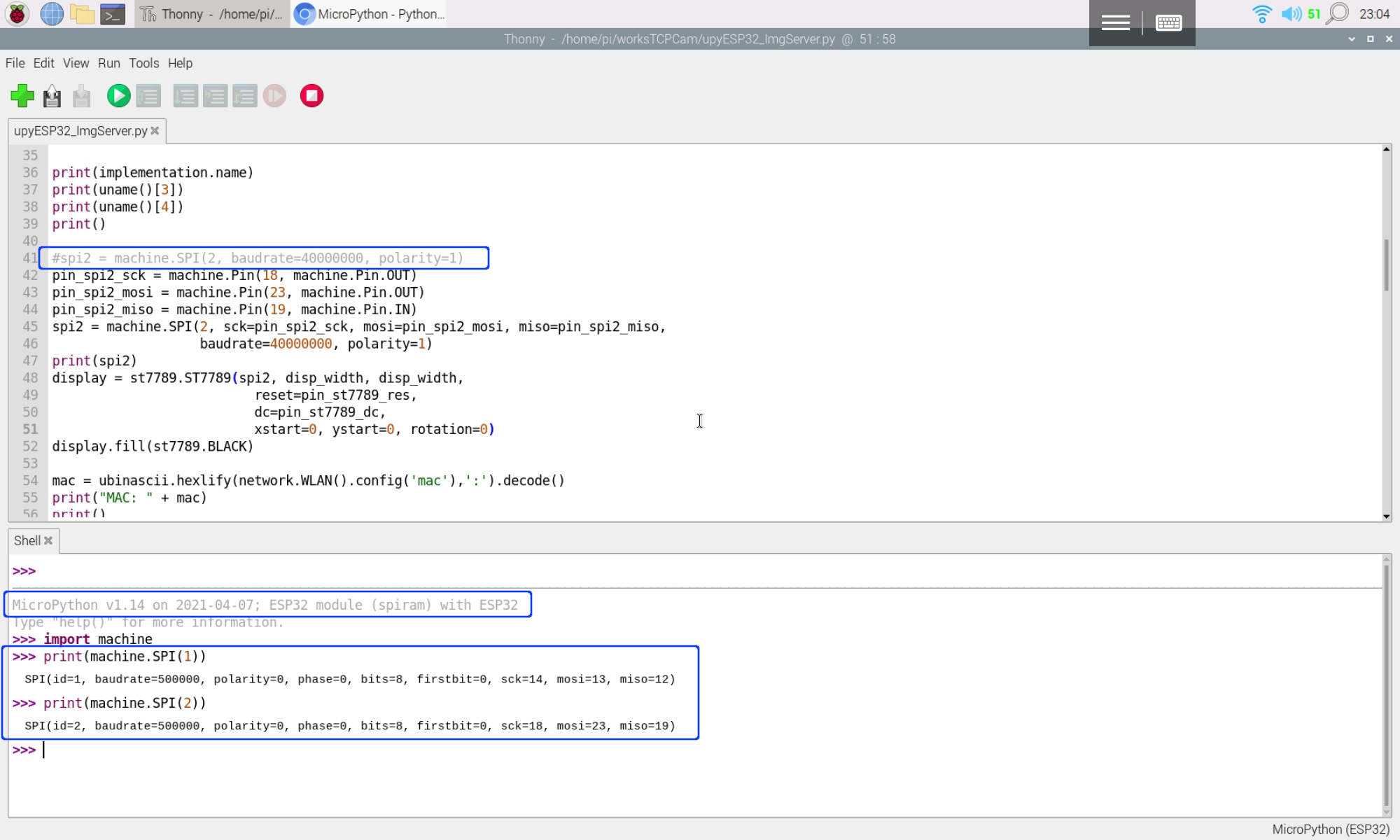
Remark about SPI@2021-04-07:

The above exercise run on version MicroPython version 'v1.14 on 2021-03-17', SPI2 defined with default pin assignment.

Recently, I tested it on 'MicroPython v1.14 2021-02-02' (stable version esp32spiram-idf4-20210202-v1.14.bin). It's founded there are NO default pin assigned to SPI.


So you have to define the pins in your code,like this:
pin_spi2_sck = machine.Pin(18, machine.Pin.OUT)
pin_spi2_mosi = machine.Pin(23, machine.Pin.OUT)
pin_spi2_miso = machine.Pin(19, machine.Pin.IN)
spi2 = machine.SPI(2, sck=pin_spi2_sck, mosi=pin_spi2_mosi, miso=pin_spi2_miso,
                   baudrate=40000000, polarity=1)
On current latest unstable version esp32spiram-20210407-unstable-v1.14-142-gcb396827f.bin, default pins are defined. Pins can be omitted using default assignment.


Saturday, March 13, 2021

RPi Pico + ESP32-S remote control ESP32-DevKitC via WiFi TCP, using MicroPython.

This exercise program Raspberry Pi Pico/MicroPython + ESP32-S (ESP-AT) as WiFi TCP client to remote control ESP32-DevKitC V4/MicroPython WiFi TCP server onboard LED.

In Client side:

ESP32-S is a wireless module based on ESP32. It's flashed with AT-command firmware ESP-AT. It's act as a WiFi co-processor. Raspberry Pi Pico/MicroPython send AT-command to ESP32-S via UART. Please note that for ESP32 flashed with ESP-AT: UART1 (IO16/IO17) is used to send AT commands and receive AT responses, connected to GP0/GP1 of Pico.

Pico GP15 connected to ESP32-S EN pin, to reset it in power up.

Pico GP16 is used control remote LED.

In Server side:

ESP32-DevKitC V4 (with ESP32-WROVER-E module)/MicroPython is programed as WiFi server, receive command from client to turn ON/OFF LED accordingly.

Connection:


MicroPython code:

Client side, mpyPico_ESP32S_remoteCli_.py run on Raspberry Pi Pico.
import uos
import machine
import utime
"""
Raspberry Pi Pico/MicroPython + ESP32-S exercise

ESP32-S with AT-command firmware (ESP-AT):
---------------------------------------------------
AT version:2.1.0.0(883f7f2 - Jul 24 2020 11:50:07)
SDK version:v4.0.1-193-ge7ac221
compile time(0ad6331):Jul 28 2020 02:47:21
Bin version:2.1.0WROM-3)
---------------------------------------------------

Pico send AT command to ESP32-S via UART,
Send command to server (ESP32/MicroPython)
to turn ON/OFF LED on server.
---------------------------------------------------
Connection:
powered by separated power supply
Pico                  ESP32-S
GND                   GND
GP0 (TX) (pin 1)      IO16 (RXD)
GP1 (RX) (pin 2)      IO17 (TXD)
GP15 (pin 20)         EN

GP16 (pin 21) button
---------------------------------------------------
"""
#server port & ip hard-coded,
#have to match with server side setting
server_ip="192.168.4.1"
server_port=8000

network_ssid = "ESP32-ssid"
network_password = "password"

ESP_EN = 15
PIN_ESP_EN = machine.Pin(ESP_EN, machine.Pin.IN, machine.Pin.PULL_UP)
DIn = machine.Pin(16, machine.Pin.IN, machine.Pin.PULL_UP)


print()
print("Machine: \t" + uos.uname()[4])
print("MicroPython: \t" + uos.uname()[3])
#indicate program started visually
led_onboard = machine.Pin(25, machine.Pin.OUT)
led_onboard.value(0)     # Toggle onboard LED 
utime.sleep(0.5)         # to indiacte program start
led_onboard.value(1)
utime.sleep(1)
led_onboard.value(0)

#Reset ESP
PIN_ESP_EN = machine.Pin(ESP_EN, machine.Pin.OUT)
PIN_ESP_EN.value(1)
utime.sleep(0.5)
PIN_ESP_EN.value(0)
utime.sleep(0.5)
PIN_ESP_EN.value(1)
PIN_ESP_EN = machine.Pin(ESP_EN, machine.Pin.IN, machine.Pin.PULL_UP)

uart = machine.UART(0, baudrate=115200)
print(uart)

RES_OK = b'OK\r\n'
len_OK = len(RES_OK)

RESULT_OK      = '0'
RESULT_TIMEOUT = '1'
def sendCMD_waitResult(cmd, timeout=2000):
    print("CMD: " + cmd)
    uart.write(cmd)

    prvMills = utime.ticks_ms()
    result = RESULT_TIMEOUT
    resp = b""
    
    while (utime.ticks_ms()-prvMills)<timeout:
        if uart.any():
            resp = b"".join([resp, uart.read(1)])
            resp_len = len(resp)
            if resp[resp_len-len_OK:]==RES_OK:
                print(RES_OK + " found!")
                result = RESULT_OK
                break
    
    print("resp:")
    try:
        print(resp.decode())
    except UnicodeError:
        print(resp)

    return result

#to make it simple to detect, RMCMD & RMSTA designed same length
#Remote Command from client to serve
RMCMD_len = 6
RMCMD_ON  = "LEDONN"   #turn LED ON
RMCMD_OFF = "LEDOFF"   #turn LED OFF
#Remote status from server to client
RMSTA_len = 6
RMSTA_timeout = "timeout" #time out without/unknown reply
RMSTA_LEDON  = "LedOnn"
RMSTA_LEDOFF = "LedOff"
"""
#Expected flow to send command to wifi is:
Pico (client) to ESP-01S    response from ESP-01S to Pico
AT+CIPSEND=<cmd len>\r\n
                            AT+CIPSEND=<cmd len>\r\n
                            OK\r\n
                            >\r\n
<cmd>
                            Recv x bytes\r\n
                            SEND OK\r\n           ---> ESP (server)
                                                  <--- ESP (server) end with OK\r\n
                            +IPD,10:<RMSTA>OK\r\n
                            +IPD,2:\r\n
"""
def sendRemoteCmd(rmcmd, timeout=2000):
    result = RMSTA_timeout
    
    if sendCMD_waitResult('AT+CIPSEND=' + str(len(rmcmd)) + '\r\n', timeout)==RESULT_OK:
        
        #dummy read '>'
        while not uart.any():
            pass
        print(uart.read(1))
        
        print("Remote CMD: " + rmcmd)
        if sendCMD_waitResult(rmcmd) == RESULT_OK:
            
            endMills = utime.ticks_ms() + timeout
            resp = b""
            
            while utime.ticks_ms()<endMills:
                if uart.any():
                    resp = b"".join([resp, uart.read(1)])
                    resp_len = len(resp)
                    if resp[resp_len-len_OK:]==RES_OK:
                        print(RES_OK + " found!")
                        rmSta=resp[resp_len-len_OK-RMSTA_len:resp_len-len_OK]
                        strRmSta=rmSta.decode()   #convert bytes to string
                        print(strRmSta)
                        if strRmSta == RMSTA_LEDON:
                            result = strRmSta
                        elif strRmSta == RMSTA_LEDOFF:
                            result = strRmSta
                        break
            print("resp:")
            try:
                print(resp.decode())
            except UnicodeError:
                print(resp)
    
    return result

def sendCMD_waitResp(cmd, timeout=2000):
    print("CMD: " + cmd)
    uart.write(cmd)
    waitResp(timeout)
    print()
    
def waitResp(timeout=2000):
    prvMills = utime.ticks_ms()
    resp = b""
    while (utime.ticks_ms()-prvMills)<timeout:
        if uart.any():
            resp = b"".join([resp, uart.read(1)])
    print("resp:")
    try:
        print(resp.decode())
    except UnicodeError:
        print(resp)
        
"""
everytimes send command to server:
- join ESP32 network
- connect to ESP32 socket
- send command to server and receive status
"""
def connectRemoteSendCmd(cmdsend):
    clearRxBuf()
    print("join wifi network: " + "ESP32-ssid")
    while sendCMD_waitResult('AT+CWJAP="' + network_ssid + '","'
                       + network_password + '"\r\n') != RESULT_OK:
        pass
    
    sendCMD_waitResp('AT+CIFSR\r\n')    #Obtain the Local IP Address
    sendCMD_waitResult('AT+CIPSTATUS\r\n')
    
    print("wifi network joint")
    print("connect socket")

    if sendCMD_waitResult('AT+CIPSTART="TCP","'
                      + server_ip
                      + '",'
                      + str(server_port) + '\r\n', timeout=5000) == RESULT_OK:
        sendCMD_waitResult('AT+CIPSTATUS\r\n')
        print("RMST: " + sendRemoteCmd(rmcmd=cmdsend))

    clearRxBuf()
    sendCMD_waitResult('AT+CIPSTATUS\r\n')
    sendCMD_waitResult('AT+CWQAP\r\n')

            
def clearRxBuf():
    print("--- clear Rx buffer ---")
    buf = b""
    while uart.any():
        buf = b"".join([buf, uart.read(1)])
    print(buf)
    print("-----------------------")
    
led_onboard.value(0)
clearRxBuf()
sendCMD_waitResult('AT\r\n')          #Test AT startup
sendCMD_waitResult('AT+CWMODE=1\r\n') #Set the Wi-Fi mode 1 = Station mode
sendCMD_waitResult('AT+CIPMUX=0\r\n') #single connection.

led_onboard.value(1)
connectRemoteSendCmd(cmdsend=RMCMD_ON)
utime.sleep(1)
connectRemoteSendCmd(cmdsend=RMCMD_OFF)

#fast toggle led 5 times to indicate startup finished
for i in range(5):
    led_onboard.value(0)
    utime.sleep(0.2)
    led_onboard.value(1)
    utime.sleep(0.2)
    led_onboard.value(0)

print("Started")
print("waiting for button")
#read digital input every 10ms
dinMills = utime.ticks_ms() + 30
prvDin = 1
debounced = False
while True:
    if utime.ticks_ms() > dinMills:
        dinMills = utime.ticks_ms() + 30
        curDin = DIn.value()
        if curDin != prvDin:
            #Din changed
            prvDin = curDin
            debounced = False
        else:
            if not debounced:
                #DIn changed for > 30ms
                debounced = True
                if curDin:
                    connectRemoteSendCmd(cmdsend=RMCMD_OFF)
                else:
                    connectRemoteSendCmd(cmdsend=RMCMD_ON)


Server side, upyESP32_AP_RemoteSvr_.py run on ESP32-DevKitC V4.
import utime
import uos
import network
import usocket
from machine import Pin

"""
ESP32/MicroPython exercise:
ESP32 act as Access Point,
and setup a simple TCP server

receive command from client and turn ON/OFF LED,
and send back status.
"""

ssid= "ESP32-ssid"
password="password"

led=Pin(13,Pin.OUT)

print("----- MicroPython -----")
for u in uos.uname():
    print(u)
print("-----------------------")

for i in range(3):
    led.on()
    utime.sleep(0.5)
    led.off()
    utime.sleep(0.5)
    

ap = network.WLAN(network.AP_IF) # Access Point
ap.config(essid=ssid,
          password=password,
          authmode=network.AUTH_WPA_WPA2_PSK) 
ap.config(max_clients=1)  # max number of client
ap.active(True)           # activate the access point

print(ap.ifconfig())
print(dir(ap))

mysocket = usocket.socket(usocket.AF_INET, usocket.SOCK_STREAM)
mysocket.setsockopt(usocket.SOL_SOCKET, usocket.SO_REUSEADDR, 1)

port = 8000
mysocket.bind(('',8000))
print("bind: " + str(port))
mysocket.listen(1)

#tomake it simple to detect, RMCMD & RMSTA designed same length
#Remote Command from client to serve
RMCMD_len = 6
RMCMD_ON  = "LEDONN"    #turn LED ON
RMCMD_OFF = "LEDOFF"   #turn LED OFF
#Remote status from server to client
RMSTA_len = 6
RMSTA_timeout = "timeout" #time out without/unknown reply
RMSTA_LEDON  = "LedOnn"
RMSTA_LEDOFF = "LedOff"

while True:
  conn, addr = mysocket.accept()
  print('Connected from: %s' % str(addr))
  print()
  request = conn.recv(1024)
  print('request: %s' % str(request))
  print()
  
  strRqs = request.decode()
  print("strRqs: "+strRqs)
  if strRqs==RMCMD_ON:
      conn.send(RMSTA_LEDON+'OK\r\n')
      led.on()
  elif strRqs==RMCMD_OFF:
      conn.send(RMSTA_LEDOFF+'OK\r\n')
      led.off()
  else:
      #unknown command
      conn.send(request.upper())
  conn.send('\r\n')
  conn.close()


Wednesday, February 24, 2021

TCP socket communication between (RPi Pico+ESP-01S) and ESP32 via WiFi

In my previous MicroPython exercises:
Pico/MicroPython + ESP-01S (AT Command) act as TCP Client connect to Raspberry Pi/Python TCP Server: Python code run on Raspberry Pi act as server. RPi Pico+ESP-01S act as client, connect and send data to server. The server once receive data, convert to upper case and send back to client.
ESP32/MicroPython exercise: act as Access Point, and setup a simple web server

In this exercise,
- the ESP32 web server code is modified to replace the role of Raspberry Pi/Python Server. Setup as WiFi Access Point, run a socket server on port 9999, wait connection from client, receive data, convert to upper case and echo back.
- RPi Pico+ESP-01S join the ESP32 WiFi network, connect to 192.168.4.1 (the default IP of ESP32 SoftAP), port 9999, send data and wait response.

Both coded in MicroPython.


In my practice as shown in the video, a Raspberry Pi 4B is used as development host for both ESP32 and Pico using MicroPython. Firstly, in Thonny, save server code (upyESP32_AP_EchoSvr_20210224a.py) on ESP32, name main.py. Switch Thonny interpreter for Pico and port. Then open Putty as serial terminal connect to ESP32 as REPL to monitor the output from ESP32. Finally, run the client code (mpyPico_ESP-01S_TCPclient_20210224a.py) in Thonny.

upyESP32_AP_EchoSvr_20210224a.py, run on ESP32 as server.
import uos
import network
import usocket
"""
ESP32/MicroPython exercise:
ESP32 act as Access Point,
and setup a simple TCP echo server

ref:
MicroPython usocket – socket module
https://docs.micropython.org/en/latest/library/usocket.html
"""

ssid= "ESP32-ssid"
password="password"

print("----- MicroPython -----")
for u in uos.uname():
    print(u)
print("-----------------------")

ap = network.WLAN(network.AP_IF) # Access Point
ap.config(essid=ssid,
          password=password,
          authmode=network.AUTH_WPA_WPA2_PSK) 
ap.config(max_clients=1)  # max number of client
ap.active(True)           # activate the access point

print(ap.ifconfig())
print(dir(ap))

mysocket = usocket.socket(usocket.AF_INET, usocket.SOCK_STREAM)
mysocket.setsockopt(usocket.SOL_SOCKET, usocket.SO_REUSEADDR, 1)

mysocket.bind(('', 9999))
mysocket.listen(1)

while True:
  conn, addr = mysocket.accept()
  print('Connected from: %s' % str(addr))
  print()
  request = conn.recv(1024)
  print('request: %s' % str(request))
  print()
  conn.send(request.upper())
  conn.send('\r\n')
  conn.close()

mpyPico_ESP-01S_TCPclient_20210224a.py, run on Raspberry Pi Pico, as client.
import uos
import machine
import utime
"""
Raspberry Pi Pico/MicroPython + ESP-01S exercise

ESP-01S(ESP8266) with AT-command firmware:
AT version:1.7.4.0(May 11 2020 19:13:04)

Pico send AT command to ESP-01S via UART,
- set in station mode
- join AP
- connect to server ip:port 9999
- send text and wait response
"""
#server port & ip hard-coded,
#have to match with server side setting
server_ip="192.168.4.1"
server_port=9999

print()
print("Machine: \t" + uos.uname()[4])
print("MicroPython: \t" + uos.uname()[3])

#indicate program started visually
led_onboard = machine.Pin(25, machine.Pin.OUT)
led_onboard.value(0)     # onboard LED OFF/ON for 0.5/1.0 sec
utime.sleep(0.5)
led_onboard.value(1)
utime.sleep(1.0)
led_onboard.value(0)

uart0 = machine.UART(0, baudrate=115200)
print(uart0)

def sendCMD_waitResp(cmd, uart=uart0, timeout=2000):
    print("CMD: " + cmd)
    uart.write(cmd)
    waitResp(uart, timeout)
    print()
    
def waitResp(uart=uart0, timeout=2000):
    prvMills = utime.ticks_ms()
    resp = b""
    while (utime.ticks_ms()-prvMills)<timeout:
        if uart.any():
            resp = b"".join([resp, uart.read(1)])
    print("resp:")
    try:
        print(resp.decode())
    except UnicodeError:
        print(resp)
        
# send CMD to uart,
# wait and show response without return
def sendCMD_waitAndShow(cmd, uart=uart0):
    print("CMD: " + cmd)
    uart.write(cmd)
    while True:
        print(uart.readline())
        
def espSend(text="test", uart=uart0):
    sendCMD_waitResp('AT+CIPSEND=' + str(len(text)) + '\r\n')
    sendCMD_waitResp(text)
        
def XmonitorESP(uart=uart0):
    """
    while True:
        line=uart.readline()
        try:
            print(line.decode())
        except UnicodeError:
            print(line)
    """
    while True:
        if uart.any():
            print(uart.read(1))
    
sendCMD_waitResp('AT\r\n')          #Test AT startup
sendCMD_waitResp('AT+GMR\r\n')      #Check version information
#sendCMD_waitResp('AT+RESTORE\r\n')  #Restore Factory Default Settings

sendCMD_waitResp('AT+CWMODE?\r\n')  #Query the Wi-Fi mode
sendCMD_waitResp('AT+CWMODE=1\r\n') #Set the Wi-Fi mode 1 = Station mode
#sendCMD_waitResp('AT+CWMODE=2\r\n') #Set the Wi-Fi mode 2 = S0ftAP mode
sendCMD_waitResp('AT+CWMODE?\r\n')  #Query the Wi-Fi mode again

#sendCMD_waitResp('AT+CWLAP\r\n', timeout=10000) #List available APs
sendCMD_waitResp('AT+CWJAP="ESP32-ssid","password"\r\n', timeout=5000) #Connect to AP
sendCMD_waitResp('AT+CIFSR\r\n')    #Obtain the Local IP Address
#sendCMD_waitResp('AT+CIPSTART="TCP","192.168.12.147",9999\r\n')
sendCMD_waitResp('AT+CIPSTART="TCP","' +
                 server_ip +
                 '",' +
                 str(server_port) +
                 '\r\n')
espSend()

while True:
    print('Enter something:')
    msg = input()
    #sendCMD_waitResp('AT+CIPSTART="TCP","192.168.12.147",9999\r\n')
    sendCMD_waitResp('AT+CIPSTART="TCP","' +
                 server_ip +
                 '",' +
                 str(server_port) +
                 '\r\n')
    espSend(msg)

Next:


Monday, February 22, 2021

ESP32/MicroPython exercise: act as Access Point, and setup a simple web server


With MicroPython installed on ESP32 (ESP32-DevKitC V4), it's a exercise to act as Access Point, and setup a simple web server.


upyESP32_AP_WebSvr_20210223a.py
import uos
import network
import usocket
"""
ESP32/MicroPython exercise:
ESP32 act as Access Point,
and setup a simple web server

ref:
MicroPython usocket – socket module
https://docs.micropython.org/en/latest/library/usocket.html
"""

ssid= "ESP32-ssid"
password="password"

print("----- MicroPython -----")
for u in uos.uname():
    print(u)
print("-----------------------")

ap = network.WLAN(network.AP_IF) # Access Point
ap.config(essid=ssid,password=password,authmode=network.AUTH_WPA_WPA2_PSK) 
ap.config(max_clients=1)  # max number of client
ap.active(True)           # activate the access point

print(ap.ifconfig())
print(dir(ap))

def get_html(fromip):
    html_head="""<HTML><HEAD>
        <meta name="viewport" content="width=device-width, initial-scale=1">
        </HEAD>
        <BODY><b>Hello ESP32/MicroPython</b><br/>"""
    html_end="""</BODY>
        </HTML>"""
    html=html_head+"your ip: "+fromip+html_end
    return html


mysocket = usocket.socket(usocket.AF_INET, usocket.SOCK_STREAM)
mysocket.setsockopt(usocket.SOL_SOCKET, usocket.SO_REUSEADDR, 1)

mysocket.bind(('', 80))
mysocket.listen(1)

while True:
  conn, addr = mysocket.accept()
  print('Connected from: %s' % str(addr))
  print()
  request = conn.recv(1024)
  print('request: %s' % str(request))
  print()
  conn.send(get_html(addr[0]))
  conn.close()


OSError: [Errno 98] EADDRINUSE

 It can be noticed that I have the  following code before mysocket.bind():
mysocket.setsockopt(usocket.SOL_SOCKET, usocket.SO_REUSEADDR, 1)
Without this code, error of "OSError: [Errno 98] EADDRINUSE" will be thrown sometimes; such as Run the program > client connect and load the web page > then re-start the program.

This code fix it in my case.


Next:

Install MicroPython on ESP32 using Thonny Python IDE, on Raspberry Pi.

Steps to install MicroPython firmware on ESP32 (ESP32-DevKitC V4, with ESP32-WROVER-E) using Thonny Python IDE, on Raspberry Pi/Raspberry Pi OS(32-bit). Include install esptool plug-ins.

Visit http://micropython.org/download/, scroll down to select Generic ESP32 module.
Download firmware (.bin) using either ESP-IDF v3.x or v4.x.

There are various daily firmware for ESP32-based boards, with separate firmware for boards with and without external SPIRAM, using either ESP-IDF v3.x or v4.x.

Non-SPIRAM firmware will work on any board, whereas SPIRAM enabled firmware will only work on boards with 4MiB of external pSRAM.

And currently,
Firmware built with ESP-IDF v4.x, with support for BLE and PPP, but no LAN.
Firmware built with ESP-IDF v3.x, with support for BLE, LAN and PPP. MicroPython v1.14 was the last version to support ESP-IDF v3.x.

If in doubt use v4.x.

Run Thonny

Run in Raspberry Pi OS Start Menu:
> programming > Thonny Python IDE

Install esptool plus-ins:

In Thonny menu:
> Tools > Manager plug-ins...
Search and install esptool

Install MicroPython firmware:

In Thonny menu:
> Run > Select Interpreter...

Select MicroPython (ESP32) from the interpreter or device drop-down box.
Click Install or Update firmware.

Select the USB port connected to ESP32.
Browse to load firmware.
Click Install.

Once Done, MicroPython installed on ESP32.

Example:

upyESP32_scan.py, example to scan available WiFi networks.
import uos
import network

print("----- MicroPython -----")
for u in uos.uname():
    print(u)
print("-----------------------")

sta_if = network.WLAN(network.STA_IF)
print(sta_if)
sta_if.active(True)
for ap in sta_if.scan():
    print(ap)

upyESP32_connect.py, example to connect WiFi network.
import uos
import network

print("----- MicroPython -----")
for u in uos.uname():
    print(u)
print("-----------------------")

def do_connect():
    sta_if = network.WLAN(network.STA_IF)
    if not sta_if.isconnected():
        print('connecting to network...')
        sta_if.active(True)
        sta_if.connect('ssid', 'password')
        while not sta_if.isconnected():
            pass
    print('network config:', sta_if.ifconfig())
    
do_connect()


Next:

Friday, February 5, 2021

ESP32 BLE Client remote control Raspberry Pi Pico/HC-08 via Bluetooth

Previous exercise show how Raspberry Pi/Python remote control LED on Raspberry Pi Pico/MicroPython with HC-08. It's a ESP32 (Arduino framework) implementation on the client side, connect and send command to Pico/HC-08 BLE server to turn on/off the LED.

The code modified from Arduino IDE's Examples > ESP32 BLE Arduino > BLE_client. To make it simple, just apply minimum change to search target UUIDs, connect to BLE server and send commands ("#LEDON\r\n"/"#LEDOFF\r\n") to toggle LED repeatedly.

The main point is BLE_client example assume the BLE server have one UUID for both advertise and service, both on HC-08 have two separated UUIDs for search (LUUID) and service(SUUID). So I have to define LUUID and SUUID separately. I fix it by guessing and trying, not sure is it a correct practice or not.


Tested on ESP32-DevKitC V4, with Raspberry Pi Pico/HC-08 BLE server.

Arduino code run on ESP32, ESP32_BLE_client_HC08.ino

/**
 * A BLE client example that is rich in capabilities.
 * There is a lot new capabilities implemented.
 * author unknown
 * updated by chegewara
 */

#include "BLEDevice.h"
//#include "BLEScan.h"

//Following UUIDs have to match with
// HC-08 LUUID/SUUID/TUUID
// The remote service we wish to connect to.
static BLEUUID  LUUID("FFF0");
static BLEUUID  SUUID("FFE0");
// The characteristic of the remote service we are interested in.
static BLEUUID  charUUID("FFE1");

static boolean doConnect = false;
static boolean connected = false;
static boolean doScan = false;
static BLERemoteCharacteristic* pRemoteCharacteristic;
static BLEAdvertisedDevice* myDevice;

boolean onLED = true;

static void notifyCallback(
  BLERemoteCharacteristic* pBLERemoteCharacteristic,
  uint8_t* pData,
  size_t length,
  bool isNotify) {
    Serial.print("Notify callback for characteristic ");
    Serial.print(pBLERemoteCharacteristic->getUUID().toString().c_str());
    Serial.print(" of data length ");
    Serial.println(length);
    Serial.print("data: ");
    Serial.println((char*)pData);
}

class MyClientCallback : public BLEClientCallbacks {
  void onConnect(BLEClient* pclient) {
  }

  void onDisconnect(BLEClient* pclient) {
    connected = false;
    Serial.println("onDisconnect");
  }
};

bool connectToServer() {
    Serial.print("Forming a connection to ");
    Serial.println(myDevice->getAddress().toString().c_str());
    
    BLEClient*  pClient  = BLEDevice::createClient();
    Serial.println(" - Created client");

    pClient->setClientCallbacks(new MyClientCallback());

    // Connect to the remove BLE Server.
    pClient->connect(myDevice);  
    // if you pass BLEAdvertisedDevice instead of address,
    //it will be recognized type of peer device address (public or private)
    
    Serial.println(" - Connected to server");

    // Obtain a reference to the service we are after in the remote BLE server.
    BLERemoteService* pRemoteService = pClient->getService(SUUID);
    if (pRemoteService == nullptr) {
      Serial.print("Failed to find our search UUID: ");
      Serial.println(SUUID.toString().c_str());
      pClient->disconnect();
      return false;
    }
    Serial.println(" - Found our service");


    // Obtain a reference to the characteristic in the service of the remote BLE server.
    pRemoteCharacteristic = pRemoteService->getCharacteristic(charUUID);
    if (pRemoteCharacteristic == nullptr) {
      Serial.print("Failed to find our characteristic UUID: ");
      Serial.println(charUUID.toString().c_str());
      pClient->disconnect();
      return false;
    }
    Serial.println(" - Found our characteristic");

    // Read the value of the characteristic.
    if(pRemoteCharacteristic->canRead()) {
      std::string value = pRemoteCharacteristic->readValue();
      Serial.print("The characteristic value was: ");
      Serial.println(value.c_str());
    }

    if(pRemoteCharacteristic->canNotify())
      pRemoteCharacteristic->registerForNotify(notifyCallback);

    connected = true;
    return true;
}
/**
 * Scan for BLE servers and find the first one that advertises the service we are looking for.
 */
class MyAdvertisedDeviceCallbacks: public BLEAdvertisedDeviceCallbacks {
 /**
   * Called for each advertising BLE server.
   */
  void onResult(BLEAdvertisedDevice advertisedDevice) {
    Serial.print("BLE Advertised Device found: ");
    Serial.println(advertisedDevice.toString().c_str());

    //for information
    Serial.println("advertisedDevice.haveServiceUUID(): " + 
                      String(advertisedDevice.haveServiceUUID()));
    Serial.println("advertisedDevice.isAdvertisingService(LUUID): " + 
                      String(advertisedDevice.isAdvertisingService(LUUID)));

    // We have found a device, let us now see if it contains the service we are looking for.
    if (advertisedDevice.haveServiceUUID() && advertisedDevice.isAdvertisingService(LUUID)) {

      BLEDevice::getScan()->stop();
      myDevice = new BLEAdvertisedDevice(advertisedDevice);
      doConnect = true;
      doScan = true;

    } // Found our server
  } // onResult
}; // MyAdvertisedDeviceCallbacks


void setup() {
  Serial.begin(115200);
  Serial.println("Starting Arduino BLE Client application...");
  BLEDevice::init("");

  // Retrieve a Scanner and set the callback we want to use to be informed when we
  // have detected a new device.  Specify that we want active scanning and start the
  // scan to run for 5 seconds.
  BLEScan* pBLEScan = BLEDevice::getScan();
  pBLEScan->setAdvertisedDeviceCallbacks(new MyAdvertisedDeviceCallbacks());
  pBLEScan->setInterval(1349);
  pBLEScan->setWindow(449);
  pBLEScan->setActiveScan(true);
  pBLEScan->start(5, false);

} // End of setup.


// This is the Arduino main loop function.
void loop() {
  // If the flag "doConnect" is true then we have scanned for and found the desired
  // BLE Server with which we wish to connect.  Now we connect to it.  Once we are 
  // connected we set the connected flag to be true.
  if (doConnect == true) {
    if (connectToServer()) {
      Serial.println("We are now connected to the BLE Server.");
    } else {
      Serial.println("We have failed to connect to the server; there is nothin more we will do.");
    }
    doConnect = false;
  }

  // If we are connected to a peer BLE Server, 
  // update the characteristic each time we are reached
  // to toggle LED.
  if (connected) {
    String newValue;

    if(onLED){
      onLED = false;
      newValue = "#LEDON\r\n";
    }else{
      onLED = true;
      newValue = "#LEDOFF\r\n";
    }
    
    Serial.println("Setting new characteristic value to \"" + newValue + "\"");
    
    // Set the characteristic's value to be the array of bytes that is actually a string.
    pRemoteCharacteristic->writeValue(newValue.c_str(), newValue.length());
  }else if(doScan){
    BLEDevice::getScan()->start(0);  
    // this is just eample to start scan after disconnect, 
    // most likely there is better way to do it in arduino
  }
  
  delay(1000); // Delay a second between loops.
} // End of loop


The Raspberry Pi Pico/MicroPython code is listed in last exercise "Raspberry Pi/Python remote control LED on Raspberry Pi Pico/MicroPython with HC-08 + ILI9341 SPI Display via Bluetooth", without changed.