Raspberry Pi Pico (RP2040) running CircuitPython 7.3.2, to drive 0.96" 128x64 SSD1306 SPI OLED using displayio. Check here.
Monday, August 8, 2022
Saturday, July 16, 2022
Fixed: Raspberry Pi OS cannot find 5G Hz WiFi Network
Recently, when I tried 64 bit Raspberry Pi OS (Bullseye) on Raspberry Pi
4B/4G, it's found 5G Hz WiFi Networks cannot be discovered, and connected.
To
fix it, I set set WiFi Country to US.
MENU > Preferences > Raspberry Pi Configuration
> select
Localisation tab
> Set WiFi Country...
> Select US United
States

remark:
I have another Raspberry Pi 4B/8G running 32 bit Raspberry Pi OS (Buster), no this problem.
I have another Raspberry Pi 4B/8G running 32 bit Raspberry Pi OS (Buster), no this problem.
Friday, July 15, 2022
Install and run 64-bit Ubuntu MATE 22.04 LTS on Raspberry Pi 4

ubuntu-mate.org
provide ready-to-run images for the Raspberry Pi SBC.
Here show
steps to prepare on Raspberry Pi 0S 64-bit (bullseye), install 64-bit Ubuntu
MATE 22.04 LTS on Raspberry Pi 4B/4G Rev 1.2 on
Kingston A400 SSD 120GB SATA (using Orico HDD Adapter Kit USB3.0
adapter). For sure, you can install on Micro SD.
To enable Boot from USB for Raspberry Pi 4, read HERE.
Thursday, July 14, 2022
Enable Boot from USB for Raspberry Pi 4/400
Raspberry Pi 4, 400 and Compute Module 4 computers use an EEPROM to boot the
system. If you want to boot your Raspberry Pi 4/400, the bootloader have to be
updated.
Steps in my practice:
Update system using apt
$ sudo apt update
$ sudo apt full-upgrade
Run raspi-config in command line (not GUI version)
$ sudo raspi-config
> Select Advanced Options
> Select Bootloader Version
> Select Latest for the latest stable bootloader release.
> Reboot
reference: https://www.raspberrypi.com/documentation/computers/raspberry-pi.html#raspberry-pi-4-boot-eeprom
rematk:
In my own case, I have two Raspberry Pi 4, tried to run Raspberry Pi OS 64 bit bullseys from Kingston A400 SSD 120GB SATA attached with Orico HDD Adapter Kit USB3.0.
case 1 - Raspberry Pi 4B/4G running 64 bit Raspberry Pi OS 11 (bullseye): no need doing anything, it boot from USB SSD automatically after reboot with original Micro SD removed.
case 2 - Raspberry Pi 4B/8G running 32 bit Raspberry Pi OS 10 (Buster): apt update/full-upgrade, and reboot cannot solve. Have to run raspi-config to select Bootloader Version (Latest I selected).
May be you will interested:
~ Install and run 64-bit Ubuntu MATE 22.04 LTS on Raspberry Pi 4
Wednesday, July 13, 2022
Raspberry Pi run on ssd via USB
Just install Raspberry Pi 0S 64-bit (bullseye), run o Raspberry Pi 4B/4G Rev
1.2.


Tested with Raspberry Pi Diagnostic SD Card Speed Test.
- The ssd used is Kingston A400 SSD 120GB SATA.
- The adapter is Orico HDD Adapter Kit USB3.0.


Log, rpdiags.txt.
Raspberry Pi Diagnostics - version 0.10
Wed Jul 13 14:40:42 2022

Test : SD Card Speed Test
Run 1
prepare-file;0;0;213472;416
seq-write;0;0;174762;341
rand-4k-write;0;0;22351;5587
rand-4k-read;16478;4119;0;0
Sequential write speed 174762 KB/sec (target 10000) - PASS
Random write speed 5587 IOPS (target 500) - PASS
Random read speed 4119 IOPS (target 1500) - PASS
Test PASS
Compare with the original MicroSD I used, Samsung EVO Plus 128G

Raspberry Pi Diagnostics - version 0.10
Wed Jul 13 17:33:10 2022

Test : SD Card Speed Test
Run 1
prepare-file;0;0;13742;26
seq-write;0;0;32621;63
rand-4k-write;0;0;3040;760
rand-4k-read;13407;3351;0;0
Sequential write speed 32621 KB/sec (target 10000) - PASS
Random write speed 760 IOPS (target 500) - PASS
Random read speed 3351 IOPS (target 1500) - PASS
Test PASS
Update firmware to enable Boot from USB
Make sure to update latest firmware and enable Boot from USB, read Enable Boot from USB for Raspberry Pi 4/400.
Tuesday, May 10, 2022
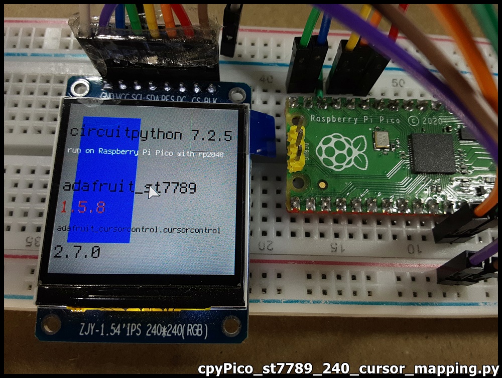
CircuitPython display cursor on displayio, work on Raspberry Pi Pico/ST7789 SPI Display.
CircuitPython exercise run on Raspberry Pi Pico + 240x240 ST7789 SPI RGB
Display, to display cursor on displayio.

Libraries needed:
- adafruit_cursorcontrol folder
- adafruit_display_text folder
- adafruit_st7789.mpy
Code:
cpyPico_st7789_240_cursor_mapping.py
- adafruit_cursorcontrol folder
- adafruit_display_text folder
- adafruit_st7789.mpy
Code:
cpyPico_st7789_240_cursor_mapping.py
cursor position are mapped to variable resistor position.
"""
Example of CircuitPython/RaspberryPi Pico
+ 240x240 ST7789 SPI RGB screen.
display cursor on displayio.

cursor position are mapped to variable resistor position

using adafruit_cursorcontrol.cursorcontrol
https://docs.circuitpython.org/projects/cursorcontrol/en/latest/api.html

Connection between Pico and
the IPS screen, with ST7789 SPI interface.
3V3  - BLK (backlight, always on)
GP11 - CS
GP12 - DC
GP13 - RES
GP15 - SDA
GP14 - SCL
3V3  - VCC
GND  - GND

AnalogIn GP26_A0 connect to variable resistor for Y
AnalogIn GP26_A1 connect to variable resistor for X
"""

import os
import sys
import board
import time
import terminalio
import displayio
import busio
from adafruit_display_text import label
import adafruit_st7789
import adafruit_cursorcontrol.cursorcontrol
from analogio import AnalogIn

print("=====================================")
info = sys.implementation[0] + ' ' + \
       os.uname()[3] + '\n' + \
       'run on ' + os.uname()[4]
print(info)
print("=====================================")
print(adafruit_st7789.__name__ + " version: " +
      adafruit_st7789.__version__)
print(adafruit_cursorcontrol.cursorcontrol.__name__
      + " version: "
      + adafruit_cursorcontrol.cursorcontrol.__version__)
print()

analog_A0 = AnalogIn(board.GP26_A0)
analog_A1 = AnalogIn(board.GP27_A1)

# Release any resources currently in use for the displays
displayio.release_displays()

tft_cs = board.GP11
tft_dc = board.GP12
tft_res = board.GP13
spi_mosi = board.GP15
spi_clk = board.GP14

display_width = 240
display_height = 240

"""
classbusio.SPI(clock: microcontroller.Pin,
                MOSI: Optional[microcontroller.Pin] = None,
                MISO: Optional[microcontroller.Pin] = None)
"""
spi = busio.SPI(spi_clk, MOSI=spi_mosi)

display_bus = displayio.FourWire(
    spi, command=tft_dc, chip_select=tft_cs, reset=tft_res
)

display = adafruit_st7789.ST7789(display_bus,
                    width=display_width, height=display_height,
                    rowstart=80,
                    rotation=180)

# Make the display context
splash = displayio.Group()
display.show(splash)

color_bitmap = displayio.Bitmap(display_width, display_height, 1)
color_palette = displayio.Palette(1)
color_palette[0] = 0xA0A0A0

bg_sprite = displayio.TileGrid(color_bitmap,
                               pixel_shader=color_palette, x=0, y=0)
splash.append(bg_sprite)

# Draw a smaller inner rectangle
inner_bitmap = displayio.Bitmap(80, 180, 1)
inner_palette = displayio.Palette(1)
inner_palette[0] = 0x0000FF
inner_sprite = displayio.TileGrid(inner_bitmap,
                                  pixel_shader=inner_palette, x=20, y=20)
splash.append(inner_sprite)

info1 = sys.implementation[0] + ' ' + os.uname()[2]
info2 = 'run on ' + os.uname()[4]

# Draw labels for CircuitPython info
text_group1 = displayio.Group(scale=2, x=5, y=40)
text1 = info1
text_area1 = label.Label(terminalio.FONT, text=text1, color=0x000000)
text_group1.append(text_area1)  # Subgroup for text scaling
#
text_group2 = displayio.Group(scale=1, x=5, y=70)
text2 = info2
text_area2 = label.Label(terminalio.FONT, text=text2, color=0xFFFFFF)
text_group2.append(text_area2)  # Subgroup for text scaling

# Draw labels for adafruit_st7789
text_group3 = displayio.Group(scale=2, x=5, y=120)
text3 = adafruit_st7789.__name__
text_area3 = label.Label(terminalio.FONT, text=text3, color=0x000000)
text_group3.append(text_area3)  # Subgroup for text scaling
#
text_group4 = displayio.Group(scale=2, x=5, y=150)
text4 = adafruit_st7789.__version__
text_area4 = label.Label(terminalio.FONT, text=text4, color=0xFF0000)
text_group4.append(text_area4)  # Subgroup for text scaling

# Draw labels for adafruit_cursorcontrol.cursorcontrol
text_group5 = displayio.Group(scale=1, x=5, y=180)
text5 = adafruit_cursorcontrol.cursorcontrol.__name__
text_area5 = label.Label(terminalio.FONT, text=text5, color=0x000000)
text_group5.append(text_area5)  # Subgroup for text scaling
#
text_group6 = displayio.Group(scale=2, x=5, y=210)
text6 = adafruit_cursorcontrol.cursorcontrol.__version__
text_area6 = label.Label(terminalio.FONT, text=text6, color=0x000000)
text_group6.append(text_area6)  # Subgroup for text scaling

splash.append(text_group1)
splash.append(text_group2)
splash.append(text_group3)
splash.append(text_group4)
splash.append(text_group5)
splash.append(text_group6)

# initialize the mouse cursor object
# place over all others
mouse_cursor = adafruit_cursorcontrol.cursorcontrol.Cursor(
    display, display_group=splash)

cnv_ratio = 240/65536

while True:
    mouse_cursor.x = (int)(analog_A1.value * cnv_ratio)
    mouse_cursor.y = (int)((64436-analog_A0.value) * cnv_ratio)

    time.sleep(0.05)

print("~ bye ~")
cpyPico_st7789_240_cursor_delta.py
variable resistor position control the cursor movement.
variable resistor position control the cursor movement.

"""
Example of CircuitPython/RaspberryPi Pico
+ 240x240 ST7789 SPI RGB screen.
display cursor on displayio.

variable resistor position control the cursor movement.

Connection between Pico and
the IPS screen, with ST7789 SPI interface.
3V3  - BLK (backlight, always on)
GP11 - CS
GP12 - DC
GP13 - RES
GP15 - SDA
GP14 - SCL
3V3  - VCC
GND  - GND

AnalogIn GP26_A0 connect to variable resistor for Y
AnalogIn GP26_A1 connect to variable resistor for X
"""

import os
import sys
import board
import time
import terminalio
import displayio
import busio
from adafruit_display_text import label
import adafruit_st7789
import adafruit_cursorcontrol.cursorcontrol
from analogio import AnalogIn

print("=====================================")
info = sys.implementation[0] + ' ' + \
       os.uname()[3] + '\n' + \
       'run on ' + os.uname()[4]
print(info)
print("=====================================")
print(adafruit_st7789.__name__ + " version: " +
      adafruit_st7789.__version__)
print(adafruit_cursorcontrol.cursorcontrol.__name__
      + " version: "
      + adafruit_cursorcontrol.cursorcontrol.__version__)
print()

analog_A0 = AnalogIn(board.GP26_A0)
analog_A1 = AnalogIn(board.GP27_A1)

# Release any resources currently in use for the displays
displayio.release_displays()

tft_cs = board.GP11
tft_dc = board.GP12
tft_res = board.GP13
spi_mosi = board.GP15
spi_clk = board.GP14

display_width = 240
display_height = 240

"""
classbusio.SPI(clock: microcontroller.Pin,
                MOSI: Optional[microcontroller.Pin] = None,
                MISO: Optional[microcontroller.Pin] = None)
"""
spi = busio.SPI(spi_clk, MOSI=spi_mosi)

display_bus = displayio.FourWire(
    spi, command=tft_dc, chip_select=tft_cs, reset=tft_res
)

display = adafruit_st7789.ST7789(display_bus,
                    width=display_width, height=display_height,
                    rowstart=80,
                    rotation=180)

# Make the display context
splash = displayio.Group()
display.show(splash)

color_bitmap = displayio.Bitmap(display_width, display_height, 1)
color_palette = displayio.Palette(1)
color_palette[0] = 0xA0A0A0

bg_sprite = displayio.TileGrid(color_bitmap,
                               pixel_shader=color_palette, x=0, y=0)
splash.append(bg_sprite)

# Draw a smaller inner rectangle
inner_bitmap = displayio.Bitmap(50, 180, 1)
inner_palette = displayio.Palette(1)
inner_palette[0] = 0x0000FF
inner_sprite = displayio.TileGrid(inner_bitmap,
                                  pixel_shader=inner_palette, x=50, y=20)
#splash.append(inner_sprite)

info1 = sys.implementation[0] + ' ' + os.uname()[2]
info2 = 'run on ' + os.uname()[4]

# Draw labels for CircuitPython info
text_group1 = displayio.Group(scale=2, x=5, y=40)
text1 = info1
text_area1 = label.Label(terminalio.FONT, text=text1, color=0x000000)
text_group1.append(text_area1)  # Subgroup for text scaling
#
text_group2 = displayio.Group(scale=1, x=5, y=70)
text2 = info2
text_area2 = label.Label(terminalio.FONT, text=text2, color=0xFFFFFF)
text_group2.append(text_area2)  # Subgroup for text scaling

# Draw labels for adafruit_st7789
text_group3 = displayio.Group(scale=2, x=5, y=120)
text3 = adafruit_st7789.__name__
text_area3 = label.Label(terminalio.FONT, text=text3, color=0x000000)
text_group3.append(text_area3)  # Subgroup for text scaling
#
text_group4 = displayio.Group(scale=2, x=5, y=150)
text4 = adafruit_st7789.__version__
text_area4 = label.Label(terminalio.FONT, text=text4, color=0xFF0000)
text_group4.append(text_area4)  # Subgroup for text scaling

# Draw labels for adafruit_cursorcontrol.cursorcontrol
text_group5 = displayio.Group(scale=1, x=5, y=180)
text5 = adafruit_cursorcontrol.cursorcontrol.__name__
text_area5 = label.Label(terminalio.FONT, text=text5, color=0x000000)
text_group5.append(text_area5)  # Subgroup for text scaling
#
text_group6 = displayio.Group(scale=2, x=5, y=210)
text6 = adafruit_cursorcontrol.cursorcontrol.__version__
text_area6 = label.Label(terminalio.FONT, text=text6, color=0x000000)
text_group6.append(text_area6)  # Subgroup for text scaling

splash.append(text_group1)
splash.append(text_group2)

# initialize the mouse cursor object
# place under inner_sprite, text_group3/4/5/6, and over all other
mouse_cursor = adafruit_cursorcontrol.cursorcontrol.Cursor(
    display, display_group=splash)

splash.append(inner_sprite)
splash.append(text_group3)
splash.append(text_group4)
splash.append(text_group5)
splash.append(text_group6)
"""
# initialize the mouse cursor object
mouse_cursor = adafruit_cursorcontrol.cursorcontrol.Cursor(
    display, display_group=splash)
"""
while True:
    offset_x = 0
    offset_y = 0
    delta_x = analog_A1.value-32768
    delta_y = analog_A0.value-32768

    if(delta_x >= 0):
        if delta_x > 30000:
            offset_x = 4
        elif delta_x > 20000:
            offset_x = 2
        elif delta_x > 10000:
            offset_x = 1
    else:
        if delta_x < -30000:
            offset_x = -4
        elif delta_x < -20000:
            offset_x = -2
        elif delta_x < -10000:
            offset_x = -1

    if(delta_y >= 0):
        if delta_y > 30000:
            offset_y = -4
        elif delta_y > 20000:
            offset_y = -2
        elif delta_y > 10000:
            offset_y = -1
    else:
        if delta_y < -30000:
            offset_y = 4
        elif delta_y < -20000:
            offset_y = 2
        elif delta_y < -10000:
            offset_y = 1

    mouse_cursor.x = mouse_cursor.x + offset_x
    mouse_cursor.y = mouse_cursor.y + offset_y

    time.sleep(0.05)

print("~ bye ~")
cpyPico_st7789_240_cursor_delta_bitmap.py
implement custom cursor bitmap.
implement custom cursor bitmap.

"""
Example of CircuitPython/RaspberryPi Pico
+ 240x240 ST7789 SPI RGB screen.
display cursor on displayio.

example to apply custom bitmap for cursor

Connection between Pico and
the IPS screen, with ST7789 SPI interface.
3V3  - BLK (backlight, always on)
GP11 - CS
GP12 - DC
GP13 - RES
GP15 - SDA
GP14 - SCL
3V3  - VCC
GND  - GND

AnalogIn GP26_A0 connect to variable resistor for Y
AnalogIn GP26_A1 connect to variable resistor for X
"""

import os
import sys
import board
import time
import terminalio
import displayio
import busio
from adafruit_display_text import label
import adafruit_st7789
import adafruit_cursorcontrol.cursorcontrol
from analogio import AnalogIn

print("=====================================")
info = sys.implementation[0] + ' ' + \
       os.uname()[3] + '\n' + \
       'run on ' + os.uname()[4]
print(info)
print("=====================================")
print(adafruit_st7789.__name__ + " version: " +
      adafruit_st7789.__version__)
print(adafruit_cursorcontrol.cursorcontrol.__name__
      + " version: "
      + adafruit_cursorcontrol.cursorcontrol.__version__)
print()

analog_A0 = AnalogIn(board.GP26_A0)
analog_A1 = AnalogIn(board.GP27_A1)

# Release any resources currently in use for the displays
displayio.release_displays()

tft_cs = board.GP11
tft_dc = board.GP12
tft_res = board.GP13
spi_mosi = board.GP15
spi_clk = board.GP14

display_width = 240
display_height = 240

"""
classbusio.SPI(clock: microcontroller.Pin,
                MOSI: Optional[microcontroller.Pin] = None,
                MISO: Optional[microcontroller.Pin] = None)
"""
spi = busio.SPI(spi_clk, MOSI=spi_mosi)

display_bus = displayio.FourWire(
    spi, command=tft_dc, chip_select=tft_cs, reset=tft_res
)

display = adafruit_st7789.ST7789(display_bus,
                    width=display_width, height=display_height,
                    rowstart=80,
                    rotation=180)

# Make the display context
splash = displayio.Group()
display.show(splash)

color_bitmap = displayio.Bitmap(display_width, display_height, 1)
color_palette = displayio.Palette(1)
color_palette[0] = 0xA0A0A0

bg_sprite = displayio.TileGrid(color_bitmap,
                               pixel_shader=color_palette, x=0, y=0)
splash.append(bg_sprite)

# Draw a smaller inner rectangle
inner_bitmap = displayio.Bitmap(50, 180, 1)
inner_palette = displayio.Palette(1)
inner_palette[0] = 0x0000FF
inner_sprite = displayio.TileGrid(inner_bitmap,
                                  pixel_shader=inner_palette, x=50, y=20)
#splash.append(inner_sprite)

info1 = sys.implementation[0] + ' ' + os.uname()[2]
info2 = 'run on ' + os.uname()[4]

# Draw labels for CircuitPython info
text_group1 = displayio.Group(scale=2, x=5, y=40)
text1 = info1
text_area1 = label.Label(terminalio.FONT, text=text1, color=0x000000)
text_group1.append(text_area1)  # Subgroup for text scaling
#
text_group2 = displayio.Group(scale=1, x=5, y=70)
text2 = info2
text_area2 = label.Label(terminalio.FONT, text=text2, color=0xFFFFFF)
text_group2.append(text_area2)  # Subgroup for text scaling

# Draw labels for adafruit_st7789
text_group3 = displayio.Group(scale=2, x=5, y=120)
text3 = adafruit_st7789.__name__
text_area3 = label.Label(terminalio.FONT, text=text3, color=0x000000)
text_group3.append(text_area3)  # Subgroup for text scaling
#
text_group4 = displayio.Group(scale=2, x=5, y=150)
text4 = adafruit_st7789.__version__
text_area4 = label.Label(terminalio.FONT, text=text4, color=0xFF0000)
text_group4.append(text_area4)  # Subgroup for text scaling

# Draw labels for adafruit_cursorcontrol.cursorcontrol
text_group5 = displayio.Group(scale=1, x=5, y=180)
text5 = adafruit_cursorcontrol.cursorcontrol.__name__
text_area5 = label.Label(terminalio.FONT, text=text5, color=0x000000)
text_group5.append(text_area5)  # Subgroup for text scaling
#
text_group6 = displayio.Group(scale=2, x=5, y=210)
text6 = adafruit_cursorcontrol.cursorcontrol.__version__
text_area6 = label.Label(terminalio.FONT, text=text6, color=0x000000)
text_group6.append(text_area6)  # Subgroup for text scaling

splash.append(text_group1)
splash.append(text_group2)

# initialize the mouse cursor object
# create custom bitmap for cursor
bmp = displayio.Bitmap(20, 20, 3)
for i in range(0, 20):
    bmp[i, (20-1)-i] = 1
    bmp[(20-1)-i, (20-1)-i] = 1
for i in range(0, 20):
    bmp[0, i] = 1
    bmp[i, 0] = 1

# initialize the mouse cursor object
# place under inner_sprite, text_group3/4/5/6, and over all other
mouse_cursor = adafruit_cursorcontrol.cursorcontrol.Cursor(
    display, display_group=splash, bmp=bmp)
"""
#use default cursor
mouse_cursor = adafruit_cursorcontrol.cursorcontrol.Cursor(
    display, display_group=splash)
"""
cursor_bitmap = mouse_cursor.cursor_bitmap
print(cursor_bitmap, cursor_bitmap.width, "x", cursor_bitmap.height)

for by in range(0, cursor_bitmap.height):
    s = str(by) + ":\t"
    for bx in range(0, cursor_bitmap.width):
        b = cursor_bitmap[bx, by]
        if b == 0:
            s = s + " " + " "
        else:
            s = s + str(b) + " "
    print(s)

splash.append(inner_sprite)
splash.append(text_group3)
splash.append(text_group4)
splash.append(text_group5)
splash.append(text_group6)
"""
# initialize the mouse cursor object
mouse_cursor = adafruit_cursorcontrol.cursorcontrol.Cursor(
    display, display_group=splash)
"""
while True:
    offset_x = 0
    offset_y = 0
    delta_x = analog_A1.value-32768
    delta_y = analog_A0.value-32768

    if(delta_x >= 0):
        if delta_x > 30000:
            offset_x = 4
        elif delta_x > 20000:
            offset_x = 2
        elif delta_x > 10000:
            offset_x = 1
    else:
        if delta_x < -30000:
            offset_x = -4
        elif delta_x < -20000:
            offset_x = -2
        elif delta_x < -10000:
            offset_x = -1

    if(delta_y >= 0):
        if delta_y > 30000:
            offset_y = -4
        elif delta_y > 20000:
            offset_y = -2
        elif delta_y > 10000:
            offset_y = -1
    else:
        if delta_y < -30000:
            offset_y = 4
        elif delta_y < -20000:
            offset_y = 2
        elif delta_y < -10000:
            offset_y = 1

    mouse_cursor.x = mouse_cursor.x + offset_x
    mouse_cursor.y = mouse_cursor.y + offset_y

    time.sleep(0.05)

print("~ bye ~")
Sunday, May 8, 2022
OpenEuler 22.03 LTS (UKUI Desktop) run on Raspberry Pi 4
OpenEuler
is an innovative platform nurtured by community collaboration. It aims to
build a unified and open OS that supports multiple processor architectures,
and to advance the hardware/software application ecosystem.
To download image of OpenEuler 22.03 LTS for Raspberry Pi, visit https://gitee.com/openeuler/raspberrypi (You can switch to English here). It provide various desktops include
UKUI, DDE, Xfce and LXDE.
UKUI is a Linux desktop built
by the KylinSoft software team over the years, primarily based on GTK and QT.
Compared to other UI interfaces, UKUI is easy to use. The components of UKUI
are small and low coupling, can run alone without relying on other suites. It
can provide user a friendly and efficient experience. UKUI supports both
x86_64 and aarch64 architectures.


This video show the steps to download image of OpenEuler 22.03 LTS (UKUI Desktop) for Raspberry Pi, boot on Raspberry Pi 4B/4G and setup changing to English, and some more.
Sunday, April 10, 2022
Raspberry Pi Pico/CircuitPython act as IMU USB Mouse, read LSM303 Accelerometer and report as mouse movement.

Base on cpyPico_lsm303_accel_inclinometer.py exercise in last post "Raspberry Pi Pico/CircuitPython, access LSM303(Accelerometer/Magnetometer) and L3GD20(Gyroscope)", added with adafruit_hid.mouse library, it is modified to act as IMU USB Mouse. User hold the 10DOF module, change orientation to move mouse pointer.
cpyPico_lsm303_accel_inclinometer_mouse.py
"""
Raspberry Pi Pico + LSM303
Act as usb_hid,
read Accelerometer and report mouse movement.

ref:
https://docs.circuitpython.org/projects/hid/en/latest/_modules/adafruit_hid/mouse.html
"""
import time
from math import atan2, degrees
import board
import adafruit_lsm303_accel
import busio
import usb_hid
from adafruit_hid.mouse import Mouse

mouse = Mouse(usb_hid.devices)

SDA=board.GP8
SCL=board.GP9
i2c = busio.I2C(SCL,SDA)  # uses board.SCL and board.SDA
sensor = adafruit_lsm303_accel.LSM303_Accel(i2c)

def vector_2_degrees(x, y):
    angle = degrees(atan2(y, x))
    if angle < 0:
        angle += 360
    return angle

def get_inclination(_sensor):
    x, y, z = _sensor.acceleration
    return vector_2_degrees(x, z), vector_2_degrees(y, z)

while True:
    angle_xz, angle_yz = get_inclination(sensor)
    #print("XZ angle = {:6.2f}deg   YZ angle = {:6.2f}deg".format(angle_xz, angle_yz))
    print(angle_xz, angle_yz)

    #LEFT/RIGHT
    if angle_xz > 120:
        mouse.move(x=+3)
    elif angle_xz > 105:
        mouse.move(x=+1)
    elif angle_xz < 60:
        mouse.move(x=-3)
    elif angle_xz < 75:
        mouse.move(x=-1)

    #UP/DOWN
    if angle_yz > 120:
        mouse.move(y=-3)
    elif angle_yz > 105:
        mouse.move(y=-1)
    elif angle_yz < 60:
        mouse.move(y=+3)
    elif angle_yz < 75:
        mouse.move(y=+1)

    time.sleep(0.02)
~ XIAO BLE Sense (Arduino framework) IMU USB Mouse
Thursday, April 7, 2022
Raspberry Pi Pico/CircuitPython, access LSM303(Accelerometer/Magnetometer) and L3GD20(Gyroscope)
The 10DOF module used in this exercise integrated with:
- LSM303DLHC
Accel/Mag
- L3GD20 Gyroscope
- BMP180 Temp/Baro

Prepare Libraries:
Visit https://circuitpython.org/libraries to download matched CircuitPython Library Bundle. Copy needed libraries to CircuitPython device /lib folder.
for LSM303(Accelerometer/Magnetometer)
cpyPico_lsm303_accel_inclinometer.py, test LSM303 Accelerometer.
# SPDX-FileCopyrightText: 2021 ladyada for Adafruit Industries
# SPDX-License-Identifier: MIT

""" Display inclination data five times per second """

import time
from math import atan2, degrees
import board
import adafruit_lsm303_accel
import busio

SDA=board.GP8
SCL=board.GP9
i2c = busio.I2C(SCL,SDA)  # uses board.SCL and board.SDA
sensor = adafruit_lsm303_accel.LSM303_Accel(i2c)

def vector_2_degrees(x, y):
    angle = degrees(atan2(y, x))
    if angle < 0:
        angle += 360
    return angle


def get_inclination(_sensor):
    x, y, z = _sensor.acceleration
    return vector_2_degrees(x, z), vector_2_degrees(y, z)


while True:
    angle_xz, angle_yz = get_inclination(sensor)
    #print("XZ angle = {:6.2f}deg   YZ angle = {:6.2f}deg".format(angle_xz, angle_yz))
    print(angle_xz, angle_yz)
    time.sleep(0.2)
next:
~ act as IMU USB Mouse, read LSM303 Accelerometer and report as mouse movement.
cpyPico_lsm303dlh_mag_compass.py, test LSM303 Magnetometer.
# SPDX-FileCopyrightText: 2021 ladyada for Adafruit Industries
# SPDX-License-Identifier: MIT

""" Display compass heading data five times per second """
import time
from math import atan2, degrees
import board
import adafruit_lsm303dlh_mag
import busio

SDA=board.GP8
SCL=board.GP9
i2c = busio.I2C(SCL, SDA)  # uses board.SCL and board.SDA
sensor = adafruit_lsm303dlh_mag.LSM303DLH_Mag(i2c)


def vector_2_degrees(x, y):
    angle = degrees(atan2(y, x))
    if angle < 0:
        angle += 360
    return angle


def get_heading(_sensor):
    magnet_x, magnet_y, _ = _sensor.magnetic
    return vector_2_degrees(magnet_x, magnet_y)


while True:
    print("heading: {:.2f} degrees".format(get_heading(sensor)))
    time.sleep(0.2)
cpyPico_st7789_240.py, verify connection/function of st7789.
"""
Example of CircuitPython/RaspberryPi Pico
to display on 1.54" IPS 240x240 (RGB) screen
with ST7789 driver via SPI interface.

Connection between Pico and
the IPS screen, with ST7789 SPI interface.
3V3  - BLK (backlight, always on)
GP11 - CS
GP12 - DC
GP13 - RES
GP15 - SDA
GP14 - SCL
3V3  - VCC
GND  - GND
"""

import os
import sys
import board
import time
import terminalio
import displayio
import busio
from adafruit_display_text import label
import adafruit_st7789

print("=====================================")
info = sys.implementation[0] + ' ' + \
       os.uname()[3] + '\n' + \
       'run on ' + os.uname()[4]
print(info)
print("=====================================")
print(adafruit_st7789.__name__ + " version: " + adafruit_st7789.__version__)
print()

# Release any resources currently in use for the displays
displayio.release_displays()

tft_cs = board.GP11
tft_dc = board.GP12
tft_res = board.GP13
spi_mosi = board.GP15
spi_clk = board.GP14

display_width = 240
display_height = 240

"""
classbusio.SPI(clock: microcontroller.Pin,
                MOSI: Optional[microcontroller.Pin] = None,
                MISO: Optional[microcontroller.Pin] = None)
"""
spi = busio.SPI(spi_clk, MOSI=spi_mosi)

display_bus = displayio.FourWire(
    spi, command=tft_dc, chip_select=tft_cs, reset=tft_res
)

display = adafruit_st7789.ST7789(display_bus,
                    width=display_width, height=display_height,
                    rowstart=80,
                    rotation=180)

# Make the display context
splash = displayio.Group()
display.show(splash)

color_bitmap = displayio.Bitmap(display_width, display_height, 1)
color_palette = displayio.Palette(1)
color_palette[0] = 0xFF0000

bg_sprite = displayio.TileGrid(color_bitmap,
                               pixel_shader=color_palette, x=0, y=0)
splash.append(bg_sprite)

# Draw a smaller inner rectangle
inner_bitmap = displayio.Bitmap(133, 238, 1)
inner_palette = displayio.Palette(1)
inner_palette[0] = 0x0000FF
inner_sprite = displayio.TileGrid(inner_bitmap,
                                  pixel_shader=inner_palette, x=1, y=1)
splash.append(inner_sprite)

info1 = sys.implementation[0] + ' ' + os.uname()[2]
info2 = 'run on ' + os.uname()[4]

# Draw a label
text_group1 = displayio.Group(scale=2, x=5, y=40)
text1 = info1
text_area1 = label.Label(terminalio.FONT, text=text1, color=0xFFFFFF)
text_group1.append(text_area1)  # Subgroup for text scaling

# Draw a label
text_group2 = displayio.Group(scale=1, x=5, y=70)
text2 = info2
text_area2 = label.Label(terminalio.FONT, text=text2, color=0xFFFFFF)
text_group2.append(text_area2)  # Subgroup for text scaling

# Draw a label
text_group3 = displayio.Group(scale=2, x=5, y=100)
text3 = adafruit_st7789.__name__
text_area3 = label.Label(terminalio.FONT, text=text3, color=0xFF0000)
text_group3.append(text_area3)  # Subgroup for text scaling
# Draw a label
text_group4 = displayio.Group(scale=2, x=5, y=130)
text4 = adafruit_st7789.__version__
text_area4 = label.Label(terminalio.FONT, text=text4, color=0x00FF00)
text_group4.append(text_area4)  # Subgroup for text scaling

splash.append(text_group1)
splash.append(text_group2)
splash.append(text_group3)
splash.append(text_group4)

time.sleep(2)
color_palette[0] = 0x00FF00

for c in range(00, 0xFF):
    time.sleep(0.001)
    col = ((0xFF-c)*0x0100) + c
    color_palette[0] = col
time.sleep(0.001)
color_palette[0] = 0x0000FF

time.sleep(1)
for c in range(00, 0xFF):
    time.sleep(0.001)
    col = 0xFF-c
    color_palette[0] = col
time.sleep(0.001)
color_palette[0] = 0x000000

time.sleep(1)
for c in range(00, 0xFF):
    time.sleep(0.001)
    col = (c * 0x010000) + (c*0x0100) + 0xFF
    inner_palette[0] = col
time.sleep(0.001)
inner_palette[0] = 0xFFFFFF

time.sleep(1)
for c in range(0xFF, 0x00, -1):
    time.sleep(0.001)
    col = (c * 0x010000) + (c*0x0100) + c
    inner_palette[0] = col
time.sleep(0.001)
inner_palette[0] = 0x000000

print("~ bye ~")
cpyPico_st7789_compass.py, read LSM303 Magnetometer, display on ST7789 in compass form.
"""
Example of CircuitPython/RaspberryPi Pico
to display on 1.54" IPS 240x240 (RGB) screen
with ST7789 driver via SPI interface.

Read from lsm303dlh and display on ST7789 in compass form.

Connection between Pico and
the IPS screen, with ST7789 SPI interface.
3V3  - BLK (backlight, always on)
GP11 - CS
GP12 - DC
GP13 - RES
GP15 - SDA
GP14 - SCL
3V3  - VCC
GND  - GND

Connection between Pico and 10DOF
3V3  - VIN
GND  - GND
SCL  - GP9
SDA  - GP8

"""

import os
import sys
import board
import time
import terminalio
import displayio
import busio
from adafruit_display_text import label
from adafruit_display_shapes.circle import Circle
from adafruit_display_shapes.line import Line
import adafruit_st7789
from math import sin, cos, radians
from math import atan2, degrees
import adafruit_lsm303dlh_mag
#import gc

print("=====================================")
info = sys.implementation[0] + ' ' + \
       os.uname()[3] + '\n' + \
       'run on ' + os.uname()[4]
print(info)
print("=====================================")
print(adafruit_st7789.__name__ + " version: "
      + adafruit_st7789.__version__)
print(adafruit_lsm303dlh_mag.__name__ + " version: "
      + adafruit_lsm303dlh_mag.__version__)
print()

# Release any resources currently in use for the displays
displayio.release_displays()

SDA = board.GP8
SCL = board.GP9
i2c_lsm303dlh = busio.I2C(SCL, SDA)

sensor_lsm303dlh = adafruit_lsm303dlh_mag.LSM303DLH_Mag(i2c_lsm303dlh)

def vector_2_degrees(x, y):
    angle = degrees(atan2(y, x))
    if angle < 0:
        angle += 360
    return angle


def get_heading(_sensor):
    magnet_x, magnet_y, _ = _sensor.magnetic
    return vector_2_degrees(magnet_x, magnet_y)

tft_cs = board.GP11
tft_dc = board.GP12
tft_res = board.GP13
spi_mosi = board.GP15
spi_clk = board.GP14

display_width = 240
display_height = 240

spi = busio.SPI(spi_clk, MOSI=spi_mosi)

display_bus = displayio.FourWire(
    spi, command=tft_dc, chip_select=tft_cs, reset=tft_res
)

display = adafruit_st7789.ST7789(display_bus,
                    width=display_width, height=display_height,
                    rowstart=80,
                    rotation=180)

# Make the display context
splash = displayio.Group()
display.show(splash)

color_bitmap = displayio.Bitmap(display_width, display_height, 1)
color_palette = displayio.Palette(1)
color_palette[0] = 0x000000

bg_sprite = displayio.TileGrid(color_bitmap,
                               pixel_shader=color_palette, x=0, y=0)
splash.append(bg_sprite)

cir_compass_cx = (int)(display_width/2)
cir_compass_cy = (int)(display_height/2)
cir_compass_r = 100
cir_compass = Circle(cir_compass_cx,
                     cir_compass_cy,
                     cir_compass_r,
                     fill=0x0000FF,
                     outline=0xFF0000)
splash.append(cir_compass)

# Draw a label
labelDir_group = displayio.Group(scale=2, x=5, y=40)
textDir = "0"
labelDir = label.Label(terminalio.FONT, text=textDir, color=0xFFFFFF)
labelDir_group.append(labelDir)
splash.append(labelDir_group)


dir_line_x1 = cir_compass_cx
dir_line_y1 = cir_compass_cy - cir_compass_r
dir_line = Line(cir_compass_cx,
                cir_compass_cy,
                dir_line_x1,
                dir_line_y1,
                0xFFFFFF)
splash.append(dir_line)
#-------------------------------


def drawDir(direction):
    global splach
    global dir_line
    global labelDir
    global display

    labelDir.text = str(direction)

    # depends on the alignmenet of your LSM303DLH and display
    dirOffset = -(direction - 180)

    x1 = (int)(cir_compass_cx +
               (cir_compass_r * cos(radians(dirOffset))))
    y1 = (int)(cir_compass_cy +
               (cir_compass_r * sin(radians(dirOffset))))

    splash.remove(dir_line)
    dir_line = Line(cir_compass_cx,
                cir_compass_cy,
                x1,
                y1,
                0xFFFFFF)

    splash.append(dir_line)
    #print(gc.mem_free())

while True:
    d = get_heading(sensor_lsm303dlh)
    #print(d)
    drawDir(d)
    time.sleep(0.1)

print("~ bye ~")
For L3GD20(Gyroscope)
This video show how to run on Raspberry Pi Pico/CircuitPython to read L3GD20(Gyroscope), using modified adafruit_l3gd20 library.
Basically, this exercise modified from CircuiyPython Libraries l3gd20_simpletest.py example, but with two proglem:
- unmatched I2C address, it'seasy to fix by adding parameter of address.
- RuntimeError: bad chip id (d3 != d4 or d7)
The accepted chip id is hard coded in adafruit_l3gd20 library. To fix it, I download the adafruit_l3gd20.py, edit to add my chip id and save as my custom library in CircuitPython device /lib folder.
cpyPico_I2C_Scan.py, verify I2C devices.
my_l3gd20.py, modified from adafruit_l3gd20 to add supporting of our chip id, save to CircuitPython device /lib folder.
cpyPico_l3gd20_simpletest.py, exercise to read L3GD20 using our library.
The accepted chip id is hard coded in adafruit_l3gd20 library. To fix it, I download the adafruit_l3gd20.py, edit to add my chip id and save as my custom library in CircuitPython device /lib folder.
cpyPico_I2C_Scan.py, verify I2C devices.
# SPDX-FileCopyrightText: 2017 Limor Fried for Adafruit Industries
#
# SPDX-License-Identifier: MIT

"""CircuitPython I2C Device Address Scan"""
# If you run this and it seems to hang, try manually unlocking
# your I2C bus from the REPL with
#  >>> import board
#  >>> board.I2C().unlock()

import time
import board
import busio

SDA = board.GP8
SCL = board.GP9
i2c = busio.I2C(SCL, SDA)

# To use default I2C bus (most boards)
#i2c = board.I2C()

# To create I2C bus on specific pins
# import busio
# i2c = busio.I2C(board.SCL1, board.SDA1)  # QT Py RP2040 STEMMA connector
# i2c = busio.I2C(board.GP1, board.GP0)    # Pi Pico RP2040

while not i2c.try_lock():
    pass

try:
    while True:
        print(
            "I2C addresses found:",
            [hex(device_address) for device_address in i2c.scan()],
        )
        time.sleep(2)

finally:  # unlock the i2c bus when ctrl-c'ing out of the loop
    i2c.unlock()
my_l3gd20.py, modified from adafruit_l3gd20 to add supporting of our chip id, save to CircuitPython device /lib folder.
# SPDX-FileCopyrightText: 2018 Michael McWethy for Adafruit Industries
#
# SPDX-License-Identifier: MIT

# https://github.com/adafruit/Adafruit_CircuitPython_L3GD20

"""
`adafruit_l3gd20`
====================================================

Adafruit 9-DOF Absolute Orientation IMU Fusion Breakout - L3GD20

This is a CircuitPython driver for the Bosch L3GD20 nine degree of freedom
inertial measurement unit module with sensor fusion.

* Author(s): Michael McWethy

Implementation Notes
--------------------

**Hardware:**

* Adafruit `L3GD20H Triple-Axis Gyro Breakout Board <https://www.adafruit.com/product/1032>`_

**Software and Dependencies:**

* Adafruit CircuitPython firmware for the supported boards:
  https://circuitpython.org/downloads


* Adafruit's Register library: https://github.com/adafruit/Adafruit_CircuitPython_Register
"""

# imports
from math import radians
from struct import unpack

from micropython import const
from adafruit_register.i2c_struct import Struct

__version__ = "0.0.0-auto.0"
__repo__ = "https://github.com/adafruit/Adafruit_CircuitPython_L3GD20.git"

L3DS20_RANGE_250DPS = const(0)
L3DS20_RANGE_500DPS = const(1)
L3DS20_RANGE_2000DPS = const(2)

L3DS20_RATE_100HZ = const(0x00)
L3DS20_RATE_200HZ = const(0x40)
L3DS20_RATE_400HZ = const(0x80)
L3DS20_RATE_800HZ = const(0xC0)

_L3GD20_REGISTER_CTRL_REG1 = const(0x20)
_L3GD20_REGISTER_CTRL_REG4 = const(0x23)

# _L3GD20_REGISTER_OUT_X_L = const(0x28)
_L3GD20_REGISTER_OUT_X_L_X80 = const(0xA8)
_L3GD20_REGISTER_OUT_X_L_X40 = const(0x68)

_ID_REGISTER = const(0x0F)

_MY_L3GD20_CHIP_ID = const(0xD3)
_L3GD20_CHIP_ID = const(0xD4)
_L3GD20H_CHIP_ID = const(0xD7)

_L3GD20_SENSITIVITY_250DPS = 0.00875  ## Roughly 22/256 for fixed point match
_L3GD20_SENSITIVITY_500DPS = 0.0175  ## Roughly 45/256
_L3GD20_SENSITIVITY_2000DPS = 0.070  ## Roughly 18/256


# pylint: disable=no-member
class L3GD20:
    """
    Driver for the L3GD20 3-axis Gyroscope sensor.

    :param int rng: a range value one of:

                    * :const:`L3DS20_RANGE_250DPS`
                    * :const:`L3DS20_RANGE_500DPS`
                    * :const:`L3DS20_RANGE_2000DPS`

                    Defaults to :const:`L3DS20_RANGE_250DPS`

    :param int rate: a rate value one of

                    * :const:`L3DS20_RATE_100HZ`
                    * :const:`L3DS20_RATE_200HZ`
                    * :const:`L3DS20_RATE_400HZ`
                    * :const:`L3DS20_RATE_800HZ`

                    Defaults to :const:`L3DS20_RATE_100HZ`
    """

    def __init__(self, rng=L3DS20_RANGE_250DPS, rate=L3DS20_RATE_100HZ):
        chip_id = self.read_register(_ID_REGISTER)
        if chip_id not in (_MY_L3GD20_CHIP_ID, _L3GD20_CHIP_ID, _L3GD20H_CHIP_ID):
            raise RuntimeError(
                "bad chip id (%x != %x, %x or %x)"
                % (chip_id, _MY_L3GD20_CHIP_ID, _L3GD20_CHIP_ID, _L3GD20H_CHIP_ID)
            )

        if rng not in (L3DS20_RANGE_250DPS, L3DS20_RANGE_500DPS, L3DS20_RANGE_2000DPS):
            raise ValueError(
                "Range value must be one of L3DS20_RANGE_250DPS, "
                "L3DS20_RANGE_500DPS, or L3DS20_RANGE_2000DPS"
            )

        # Set CTRL_REG1 (0x20)
        # ====================================================================
        # BIT  Symbol    Description                                   Default
        # ---  ------    --------------------------------------------- -------
        # 7-6  DR1#0     Output data rate
        # 5-4  BW1#0     Bandwidth selection
        #     3  PD        0 = Power-down mode, 1 = normal#sleep mode
        #     2  ZEN       Z-axis enable (0 = disabled, 1 = enabled)
        #     1  YEN       Y-axis enable (0 = disabled, 1 = enabled)
        #     0  XEN       X-axis enable (0 = disabled, 1 = enabled)

        # Switch to normal mode and enable all three channels
        self.write_register(_L3GD20_REGISTER_CTRL_REG1, rate | 0x0F)

        # Set CTRL_REG2 (0x21)
        # ====================================================================
        # BIT  Symbol    Description                                   Default
        # ---  ------    --------------------------------------------- -------
        # 5-4  HPM1#0    High-pass filter mode selection
        # 3-0  HPCF3..0  High-pass filter cutoff frequency selection

        # Nothing to do ... keep default values
        # ------------------------------------------------------------------

        #  Set CTRL_REG3 (0x22)
        # ====================================================================
        # BIT  Symbol    Description                                   Default
        # ---  ------    --------------------------------------------- -------
        #     7  I1_Int1   Interrupt enable on INT1 (0=disable,1=enable)
        #     6  I1_Boot   Boot status on INT1 (0=disable,1=enable)
        #     5  H-Lactive Interrupt active config on INT1 (0=high,1=low)
        #     4  PP_OD     Push-Pull#Open-Drain (0=PP, 1=OD)
        #     3  I2_DRDY   Data ready on DRDY#INT2 (0=disable,1=enable)
        #     2  I2_WTM    FIFO wtrmrk int on DRDY#INT2 (0=dsbl,1=enbl)
        #     1  I2_ORun   FIFO overrun int on DRDY#INT2 (0=dsbl,1=enbl)
        #     0  I2_Empty  FIFI empty int on DRDY#INT2 (0=dsbl,1=enbl)

        #  Nothing to do ... keep default values
        #  -----------------------------------------------------------------

        #  Set CTRL_REG4 (0x23)
        # ====================================================================
        # BIT  Symbol    Description                                   Default
        # ---  ------    --------------------------------------------- -------
        #     7  BDU       Block Data Update (0=continuous, 1=LSB#MSB)
        #     6  BLE       Big#Little-Endian (0=Data LSB, 1=Data MSB)
        # 5-4  FS1#0     Full scale selection
        #                                 00 = 250 dps
        #                                 01 = 500 dps
        #                                 10 = 2000 dps
        #                                 11 = 2000 dps
        #     0  SIM       SPI Mode (0=4-wire, 1=3-wire)

        # Adjust resolution if requested

        if rng == L3DS20_RANGE_250DPS:
            self.scale = _L3GD20_SENSITIVITY_250DPS
            self.write_register(_L3GD20_REGISTER_CTRL_REG4, 0x00)

        if rng == L3DS20_RANGE_500DPS:
            self.scale = _L3GD20_SENSITIVITY_500DPS
            self.write_register(_L3GD20_REGISTER_CTRL_REG4, 0x10)

        if rng == L3DS20_RANGE_2000DPS:
            self.scale = _L3GD20_SENSITIVITY_2000DPS
            self.write_register(_L3GD20_REGISTER_CTRL_REG4, 0x20)

        # ------------------------------------------------------------------

        # Set CTRL_REG5 (0x24)
        # ====================================================================
        # BIT  Symbol    Description                                   Default
        # ---  ------    --------------------------------------------- -------
        #     7  BOOT      Reboot memory content (0=normal, 1=reboot)
        #     6  FIFO_EN   FIFO enable (0=FIFO disable, 1=enable)
        #     4  HPen      High-pass filter enable (0=disable,1=enable)
        # 3-2  INT1_SEL  INT1 Selection config
        # 1-0  OUT_SEL   Out selection config

        # Nothing to do ... keep default values
        # ------------------------------------------------------------------

    @property
    def gyro(self):
        """
        x, y, z angular momentum tuple floats, rescaled appropriately for
        range selected in rad/s
        """
        raw = self.gyro_raw
        return tuple(radians(self.scale * v) for v in raw)


class L3GD20_I2C(L3GD20):
    """
    Driver for L3GD20 Gyroscope using I2C communications

    :param ~busio.I2C i2c: The I2C bus the device is connected to
    :param int rng: range value. Defaults to :const:`0x68`
    :param int rate: rate value. Defaults to :const:`L3DS20_RATE_100HZ`


    **Quickstart: Importing and using the device**

        Here is an example of using the :class:`L3GD20_I2C` class.
        First you will need to import the libraries to use the sensor

        .. code-block:: python

            import board
            import adafruit_l3gd20

        Once this is done you can define your `board.I2C` object and define your sensor object

        .. code-block:: python

            i2c = board.I2C()  # uses board.SCL and board.SDA
            sensor = adafruit_l3gd20.L3GD20_I2C(i2c)

        Now you have access to the :attr:`gyro` attribute

        .. code-block:: python

            gyro_data = sensor.gyro


    """

    gyro_raw = Struct(_L3GD20_REGISTER_OUT_X_L_X80, "<hhh")
    """Gives the raw gyro readings, in units of rad/s."""

    def __init__(
        self, i2c, rng=L3DS20_RANGE_250DPS, address=0x6B, rate=L3DS20_RATE_100HZ
    ):
        from adafruit_bus_device import (  # pylint: disable=import-outside-toplevel
            i2c_device,
        )

        self.i2c_device = i2c_device.I2CDevice(i2c, address)
        self.buffer = bytearray(2)
        super().__init__(rng, rate)

    def write_register(self, register, value):
        """
        Update a register with a byte value

        :param int register: which device register to write
        :param value: a byte to write
        """
        self.buffer[0] = register
        self.buffer[1] = value
        with self.i2c_device as i2c:
            i2c.write(self.buffer)

    def read_register(self, register):
        """
        Returns a byte value from a register

        :param register: the register to read a byte
        """
        self.buffer[0] = register
        with self.i2c_device as i2c:
            i2c.write_then_readinto(self.buffer, self.buffer, out_end=1, in_start=1)
        return self.buffer[1]


class L3GD20_SPI(L3GD20):
    """
    Driver for L3GD20 Gyroscope using SPI communications

    :param ~busio.SPI spi_busio: The SPI bus the device is connected to
    :param ~digitalio.DigitalInOut cs: digital in/out to use as chip select signal
    :param int rng: range value. Defaults to :const:`L3DS20_RANGE_250DPS`.
    :param baudrate: SPI baud rate. Defaults to :const:`100000`
    :param int rate: rate value. Defaults to :const:`L3DS20_RATE_100HZ`

    **Quickstart: Importing and using the device**

        Here is an example of using the :class:`L3GD20_SPI` class.
        First you will need to import the libraries to use the sensor

        .. code-block:: python

            import board
            import adafruit_l3gd20

        Once this is done you can define your `board.SPI` object and define your sensor object

        .. code-block:: python

            spi = board.SPI()
            sensor = adafruit_l3gd20.L3GD20_SPI(spi)

        Now you have access to the :attr:`gyro` attribute

        .. code-block:: python

            gyro_data = sensor.gyro


    """

    def __init__(
        self,
        spi_busio,
        cs,
        rng=L3DS20_RANGE_250DPS,
        baudrate=100000,
        rate=L3DS20_RATE_100HZ,
    ):  # pylint: disable=too-many-arguments
        from adafruit_bus_device import (  # pylint: disable=import-outside-toplevel
            spi_device,
        )

        self._spi = spi_device.SPIDevice(spi_busio, cs, baudrate=baudrate)
        self._spi_bytearray1 = bytearray(1)
        self._spi_bytearray6 = bytearray(6)
        super().__init__(rng, rate)

    def write_register(self, register, value):
        """
        Low level register writing over SPI, writes one 8-bit value

        :param int register: which device register to write
        :param value: a byte to write
        """
        register &= 0x7F  # Write, bit 7 low.
        with self._spi as spi:
            spi.write(bytes([register, value & 0xFF]))

    def read_register(self, register):
        """
        Low level register reading over SPI, returns a list of values

        :param register: the register to read a byte
        """
        register = (register | 0x80) & 0xFF  # Read single, bit 7 high.
        with self._spi as spi:
            self._spi_bytearray1[0] = register
            spi.write(self._spi_bytearray1)
            spi.readinto(self._spi_bytearray1)
            # Uncomment to dump bytearray:
            # print("$%02X => %s" % (register, [hex(i) for i in self._spi_bytearray1]))
            return self._spi_bytearray1[0]

    def read_bytes(self, register, buffer):
        """
        Low level register stream reading over SPI, returns a list of values

        :param register: the register to read bytes
        :param bytearray buffer: buffer to fill with data from stream
        """
        register = (register | 0x80) & 0xFF  # Read single, bit 7 high.
        with self._spi as spi:
            self._spi_bytearray1[0] = register
            spi.write(self._spi_bytearray1)
            spi.readinto(buffer)

    @property
    def gyro_raw(self):
        """Gives the dynamic rate raw gyro readings, in units rad/s."""
        buffer = self._spi_bytearray6
        self.read_bytes(_L3GD20_REGISTER_OUT_X_L_X40, buffer)
        return tuple(radians(x) for x in unpack("<hhh", buffer))
cpyPico_l3gd20_simpletest.py, exercise to read L3GD20 using our library.
# SPDX-FileCopyrightText: 2021 ladyada for Adafruit Industries
# SPDX-License-Identifier: MIT

import time
import board
import my_l3gd20
import busio

SDA = board.GP8
SCL = board.GP9
# Hardware I2C setup:
I2C = busio.I2C(SCL, SDA)  # uses board.SCL and board.SDA
# Initializes L3GD20 object using default range, 250dps
SENSOR = my_l3gd20.L3GD20_I2C(I2C, address=0x69)
# Initialize L3GD20 object using a custom range and output data rate (ODR).
# SENSOR = adafruit_l3gd20.L3GD20_I2C(
#    I2C, rng=adafruit_l3gd20.L3DS20_RANGE_500DPS, rate=adafruit_l3gd20.L3DS20_RATE_200HZ
# )

# Possible values for rng are:
# adafruit_l3gd20.L3DS20_Range_250DPS, 250 degrees per second. Default range
# adafruit_l3gd20.L3DS20_Range_500DPS, 500 degrees per second
# adafruit_l3gd20.L3DS20_Range_2000DPS, 2000 degrees per second

# Possible values for rate are:
# adafruit_l3gd20.L3DS20_RATE_100HZ, 100Hz data rate. Default data rate
# adafruit_l3gd20.L3DS20_RATE_200HZ, 200Hz data rate
# adafruit_l3gd20.L3DS20_RATE_400HZ, 400Hz data rate
# adafruit_l3gd20.L3DS20_RATE_800HZ, 800Hz data rate

# Hardware SPI setup:
# import digitalio
# CS = digitalio.DigitalInOut(board.D5)
# SPIB = board.SPI()
# SENSOR = adafruit_l3gd20.L3GD20_SPI(SPIB, CS)
# SENSOR = adafruit_l3gd20.L3GD20_I2C(
#    SPIB,
#    CS,
#    rng=adafruit_l3gd20.L3DS20_RANGE_500DPS,
#    rate=adafruit_l3gd20.L3DS20_RATE_200HZ,
# )

while True:
    #print("Angular Velocity (rad/s): {}".format(SENSOR.gyro))
    print(SENSOR.gyro[0], SENSOR.gyro[1], SENSOR.gyro[2])
    #print()
    time.sleep(1)
Thursday, March 31, 2022
Raspberry Pi Pico/MicroPython generate QR Code and display on SSD1306 I2C OLED
Run on Raspberry Pi Pico/MicroPython, to generate QR Code, and display on
SSD1306 128x64 I2C OLED.

I2C(0) is used to connect to SSD1306 I2C, scl=9 and sda=8.
For SSD1306 driver, visit https://github.com/micropython/micropython/blob/master/drivers/display/ssd1306.py to download ssd1306.py, save to Raspberry Pi Pico driver.
For QR Code, JASchilz/uQR is used. Download uQR.py and save to Raspberry Pi Pico driver.
For SSD1306 driver, visit https://github.com/micropython/micropython/blob/master/drivers/display/ssd1306.py to download ssd1306.py, save to Raspberry Pi Pico driver.
For QR Code, JASchilz/uQR is used. Download uQR.py and save to Raspberry Pi Pico driver.
mpyPico_i2c.py, simple verify I2C(0) pins and connection to SSD1306 I2C OLED.
import uos
import usys

print("====================================================")
print(usys.implementation[0],
      str(usys.implementation[1][0]) + "." +
      str(usys.implementation[1][1]) + "." +
      str(usys.implementation[1][2]))
print(uos.uname()[3])
print("run on", uos.uname()[4])
print("====================================================")

i2c0 = machine.I2C(0)
print(i2c0)
print("Available i2c devices: "+ str(i2c0.scan()))

print("~ bye ~")
mpyPico_ssd1306.py, simple test program for SSD1306 I2C OLED.
"""
Run on Raspbery Pi Pico/MicroPython
display on ssd1306 I2C OLED

connec ssd1306 using I2C(0)
scl=9
sda=8

- Libs needed:

ssd1306 library
https://github.com/micropython/micropython/blob/master/drivers/display/ssd1306.py
"""
import uos
import usys
from ssd1306 import SSD1306_I2C

print("====================================================")
print(usys.implementation[0],
      str(usys.implementation[1][0]) + "." +
      str(usys.implementation[1][1]) + "." +
      str(usys.implementation[1][2]))
print(uos.uname()[3])
print("run on", uos.uname()[4])
print("====================================================")

i2c0 = machine.I2C(0)
print(i2c0)
print("Available i2c devices: "+ str(i2c0.scan()))

WIDTH = 128
HEIGHT = 64

oled = SSD1306_I2C(WIDTH, HEIGHT, i2c0)
oled.fill(0)

oled.text(usys.implementation[0], 0, 0)

strVersion = str(usys.implementation[1][0]) + "." + \
             str(usys.implementation[1][1]) + "." + \
             str(usys.implementation[1][2])
oled.text(strVersion, 0, 10)
oled.text(uos.uname()[3], 0, 20)
oled.text(uos.uname()[4], 0, 40)
oled.show()
mpyPico_ssd1306_uQR.py, generate QR Code using uQR.py, and display on SSD1306 I2C OLED.
"""
Run on Raspbery Pi Pico/MicroPython
to generate QR code using uQR,
and display on ssd1306 I2C OLED

- Libs needed:

ssd1306 library
https://github.com/micropython/micropython/blob/master/drivers/
display/ssd1306.py

JASchilz/uQR:
https://github.com/JASchilz/uQR

remark:
in the original example on uQR to display on ssd1306, scale of 2 is used.
It's found:
- If the data is too long, the small 128x64 OLED cannot display the whole matrix.
- In my test using my phone, scale of 1 is more easy to recognize.
Such that I use scale of 1 inside the loop to generate  qr code.
"""
from uos import uname
from usys import implementation
from machine import I2C
from time import sleep
from ssd1306 import SSD1306_I2C
from uQR import QRCode

print("====================================================")
print(implementation[0],
      str(implementation[1][0]) + "." +
      str(implementation[1][1]) + "." +
      str(implementation[1][2]))
print(uname()[3])
print("run on", uname()[4])
print("====================================================")

i2c0 = I2C(0)
print(i2c0)
print("Available i2c devices: "+ str(i2c0.scan()))

WIDTH = 128
HEIGHT = 64

oled = SSD1306_I2C(WIDTH, HEIGHT, i2c0)
oled.fill(0)

oled.text("RPi Pico", 0, 0)
oled.text("MicroPython", 0, 10)
oled.text("OLED(ssd1306)", 0, 20)
oled.text("uQR exercise", 0, 40)
oled.show()

sleep(5)
qr = QRCode()

qr.add_data("uQR example")
matrix = qr.get_matrix()
print("version:", qr.version)
print("len of matrix", len(matrix))

oled.fill(1)
for y in range(len(matrix)*2):                   # Scaling the bitmap by 2
    for x in range(len(matrix[0])*2):            # because my screen is tiny.
        value = not matrix[int(y/2)][int(x/2)]   # Inverting the values because
        oled.pixel(x, y, value)                  # black is `True` in the matrix.
oled.show()

while True:
    userinput = input("\nEnter something: ")
    if userinput == "":
        break
    print(userinput)
    qr.clear()
    qr.add_data(userinput)
    matrix = qr.get_matrix()
    print("version:", qr.version)
    print("len of matrix", len(matrix))

    oled.fill(1)
    scale = 1
    for y in range(len(matrix)*scale):
        for x in range(len(matrix[0])*scale):
            value = not matrix[int(y/scale)][int(x/scale)]
            oled.pixel(x, y, value)
    oled.show()

print("~ bye ~")
mpyPico_simpletest_uQR.py, generate QR Code and display on REPL.
"""
Run on Raspbery Pi Pico/MicroPython
to generate QR code using uQR,
and display on screen

- Libs needed:

JASchilz/uQR:
https://github.com/JASchilz/uQR

"""
from uos import uname
from usys import implementation
from usys import stdout

from uQR import QRCode

print("====================================================")
print(implementation[0],
      str(implementation[1][0]) + "." +
      str(implementation[1][1]) + "." +
      str(implementation[1][2]))
print(uname()[3])
print("run on", uname()[4])
print("====================================================")

# For drawing filled rectangles to the console:
stdout = stdout
WHITE = "\x1b[1;47m  \x1b[40m"
BLACK = "  "
NORMAL = '\033[1;37;0m'

def print_QR(uqr):

    qr_matrix = uqr.get_matrix()

    print("version:", uqr.version)
    qr_height = len(qr_matrix)
    qr_width = len(qr_matrix[0])
    print("qr_height:  ", qr_height)
    print("qr_width:   ", qr_width)

    for _ in range(4):
        for _ in range(qr_width + 8): #margin on top
            stdout.write(WHITE)
        print()
    for y in range(qr_height):
        stdout.write(WHITE * 4)       #margin on right
        for x in range(len(matrix[0])):
            value = qr_matrix[int(y)][int(x)]
            if value == True:
                stdout.write(BLACK)
            else:
                stdout.write(WHITE)
        stdout.write(WHITE * 4)        #margin on left
        print()
    for _ in range(4):
        for _ in range(qr_width + 8):  #margin on bottom
            stdout.write(WHITE)
        print()
    print(NORMAL)

qr = QRCode()

qr.add_data("uQR example")
matrix = qr.get_matrix()

print_QR(qr)

while True:
    userinput = input("\nEnter something: ")
    if userinput == "":
        break
    print(userinput)
    qr.clear()
    qr.add_data(userinput)
    matrix = qr.get_matrix()

    print_QR(qr)


print("~ bye ~")
Tuesday, March 15, 2022
Raspberry Pi Pico online simulator
Wokwi is an online Electronics simulator. You can use it to simulate Arduino, ESP32, and many other popular boards, parts and sensors.
Here is a Raspberry Pi Pico (SDK) online simulator.

Wednesday, February 23, 2022
Raspberry Pi Pico/MicroPython: get MicroPython version programmatically
A simple exercise run on Raspberry Pi Pico/MicroPython to get installed MicroPython version programmatically.

mpyPico_info.py
import uos
import usys

class color:
    BLACK =   '\033[1;30;48m'
    RED =     '\033[1;31;48m'
    GREEN =   '\033[1;32;48m'
    YELLOW =  '\033[1;33;48m'
    BLUE =    '\033[1;34;48m'
    MAGENTA = '\033[1;35;48m'
    CYAN =    '\033[1;36;48m'
    END =    '\033[1;37;0m'

#print(uos.uname())
#print(usys.implementation)

print("====================================================")
print(color.BLUE, usys.implementation[0],
      str(usys.implementation[1][0]) + "." +
      str(usys.implementation[1][1]) + "." +
      str(usys.implementation[1][2]), color.END)
print(uos.uname()[3])
print("run on", color.RED, uos.uname()[4], color.END)
print("====================================================")
~ more exercises for Raspberry Pi Pico
Saturday, February 5, 2022
How to check running Raspberry Pi OS version, 32 bit or 64 bit.
To check the bit size (32 bit or 64 bit) of the running Raspberry Pi OS, you can enter the commands:
$ uname -m
aarch64
or:
$ arch
aarch64
You can also check the bit size of the Linux kernel with:
$ getconf LONG_BIT
64
Tested on Raspberry Pi 4B running Raspberry Pi OS 64-bit (bullseye):

Tested on Raspberry Pi 4B running Raspberry Pi OS 32-bit (buster):

Subscribe to:
Posts (Atom)