Showing posts with label SSD1306 I2C OLED. Show all posts

Thursday, March 31, 2022

Raspberry Pi Pico/MicroPython generate QR Code and display on SSD1306 I2C OLED

Run on Raspberry Pi Pico/MicroPython, to generate QR Code, and display on SSD1306 128x64 I2C OLED.


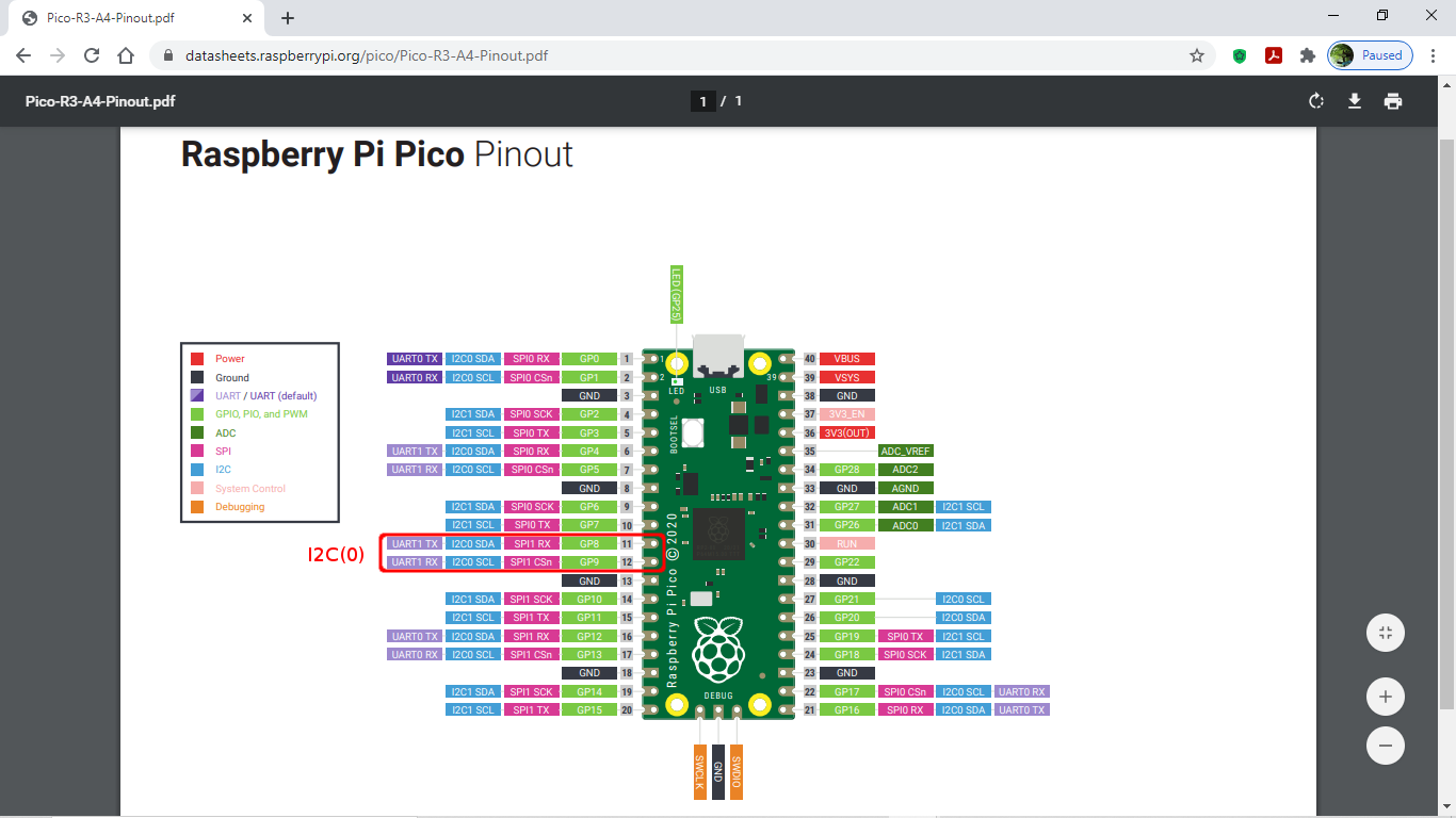
I2C(0) is used to connect to SSD1306 I2C, scl=9 and sda=8.

For SSD1306 driver, visit https://github.com/micropython/micropython/blob/master/drivers/display/ssd1306.py to download ssd1306.py, save to Raspberry Pi Pico driver.

For QR Code, JASchilz/uQR is used. Download uQR.py and save to Raspberry Pi Pico driver.


mpyPico_i2c.py, simple verify I2C(0) pins and connection to SSD1306 I2C OLED.
import uos
import usys

print("====================================================")
print(usys.implementation[0],
      str(usys.implementation[1][0]) + "." +
      str(usys.implementation[1][1]) + "." +
      str(usys.implementation[1][2]))
print(uos.uname()[3])
print("run on", uos.uname()[4])
print("====================================================")

i2c0 = machine.I2C(0)
print(i2c0)
print("Available i2c devices: "+ str(i2c0.scan()))

print("~ bye ~")

mpyPico_ssd1306.py, simple test program for SSD1306 I2C OLED.
"""
Run on Raspbery Pi Pico/MicroPython
display on ssd1306 I2C OLED

connec ssd1306 using I2C(0)
scl=9
sda=8

- Libs needed:

ssd1306 library
https://github.com/micropython/micropython/blob/master/drivers/display/ssd1306.py
"""
import uos 
import usys
from ssd1306 import SSD1306_I2C

print("====================================================")
print(usys.implementation[0],
      str(usys.implementation[1][0]) + "." +
      str(usys.implementation[1][1]) + "." +
      str(usys.implementation[1][2]))
print(uos.uname()[3])
print("run on", uos.uname()[4])
print("====================================================")

i2c0 = machine.I2C(0)
print(i2c0)
print("Available i2c devices: "+ str(i2c0.scan()))

WIDTH = 128
HEIGHT = 64

oled = SSD1306_I2C(WIDTH, HEIGHT, i2c0)
oled.fill(0)

oled.text(usys.implementation[0], 0, 0)

strVersion = str(usys.implementation[1][0]) + "." + \
             str(usys.implementation[1][1]) + "." + \
             str(usys.implementation[1][2])
oled.text(strVersion, 0, 10)
oled.text(uos.uname()[3], 0, 20)
oled.text(uos.uname()[4], 0, 40)
oled.show()

mpyPico_ssd1306_uQR.py, generate QR Code using uQR.py, and display on SSD1306 I2C OLED.
"""
Run on Raspbery Pi Pico/MicroPython
to generate QR code using uQR,
and display on ssd1306 I2C OLED

- Libs needed:

ssd1306 library
https://github.com/micropython/micropython/blob/master/drivers/
display/ssd1306.py

JASchilz/uQR:
https://github.com/JASchilz/uQR

remark:
in the original example on uQR to display on ssd1306, scale of 2 is used.
It's found:
- If the data is too long, the small 128x64 OLED cannot display the whole matrix.
- In my test using my phone, scale of 1 is more easy to recognize.
Such that I use scale of 1 inside the loop to generate  qr code.
"""
from uos import uname
from usys import implementation
from machine import I2C
from time import sleep
from ssd1306 import SSD1306_I2C
from uQR import QRCode

print("====================================================")
print(implementation[0],
      str(implementation[1][0]) + "." +
      str(implementation[1][1]) + "." +
      str(implementation[1][2]))
print(uname()[3])
print("run on", uname()[4])
print("====================================================")

i2c0 = I2C(0)
print(i2c0)
print("Available i2c devices: "+ str(i2c0.scan()))

WIDTH = 128
HEIGHT = 64

oled = SSD1306_I2C(WIDTH, HEIGHT, i2c0)
oled.fill(0)

oled.text("RPi Pico", 0, 0)
oled.text("MicroPython", 0, 10)
oled.text("OLED(ssd1306)", 0, 20)
oled.text("uQR exercise", 0, 40)
oled.show()

sleep(5)
qr = QRCode()

qr.add_data("uQR example")
matrix = qr.get_matrix()
print("version:", qr.version)
print("len of matrix", len(matrix))

oled.fill(1)
for y in range(len(matrix)*2):                   # Scaling the bitmap by 2
    for x in range(len(matrix[0])*2):            # because my screen is tiny.
        value = not matrix[int(y/2)][int(x/2)]   # Inverting the values because
        oled.pixel(x, y, value)                  # black is `True` in the matrix.
oled.show()

while True:
    userinput = input("\nEnter something: ")
    if userinput == "":
        break
    print(userinput)
    qr.clear()
    qr.add_data(userinput)
    matrix = qr.get_matrix()
    print("version:", qr.version)
    print("len of matrix", len(matrix))
    
    oled.fill(1)
    scale = 1
    for y in range(len(matrix)*scale): 
        for x in range(len(matrix[0])*scale): 
            value = not matrix[int(y/scale)][int(x/scale)]
            oled.pixel(x, y, value)
    oled.show()
    
print("~ bye ~")

mpyPico_simpletest_uQR.py, generate QR Code and display on REPL.
"""
Run on Raspbery Pi Pico/MicroPython
to generate QR code using uQR,
and display on screen

- Libs needed:

JASchilz/uQR:
https://github.com/JASchilz/uQR

"""
from uos import uname
from usys import implementation
from usys import stdout

from uQR import QRCode

print("====================================================")
print(implementation[0],
      str(implementation[1][0]) + "." +
      str(implementation[1][1]) + "." +
      str(implementation[1][2]))
print(uname()[3])
print("run on", uname()[4])
print("====================================================")

# For drawing filled rectangles to the console:
stdout = stdout
WHITE = "\x1b[1;47m  \x1b[40m"
BLACK = "  "
NORMAL = '\033[1;37;0m'

def print_QR(uqr):

    qr_matrix = uqr.get_matrix()
    
    print("version:", uqr.version)
    qr_height = len(qr_matrix)
    qr_width = len(qr_matrix[0])
    print("qr_height:  ", qr_height)
    print("qr_width:   ", qr_width)

    for _ in range(4):
        for _ in range(qr_width + 8): #margin on top
            stdout.write(WHITE)
        print()
    for y in range(qr_height):
        stdout.write(WHITE * 4)       #margin on right
        for x in range(len(matrix[0])):
            value = qr_matrix[int(y)][int(x)]
            if value == True:
                stdout.write(BLACK)
            else:
                stdout.write(WHITE)
        stdout.write(WHITE * 4)        #margin on left
        print()
    for _ in range(4):
        for _ in range(qr_width + 8):  #margin on bottom
            stdout.write(WHITE)
        print()
    print(NORMAL)
        
qr = QRCode()

qr.add_data("uQR example")
matrix = qr.get_matrix()

print_QR(qr)

while True:
    userinput = input("\nEnter something: ")
    if userinput == "":
        break
    print(userinput)
    qr.clear()
    qr.add_data(userinput)
    matrix = qr.get_matrix()
    
    print_QR(qr)


print("~ bye ~")
More exercise for Raspberry Pi Pico

Thursday, February 18, 2021

RPi Pico/CircuitPython x AHT20+BMP280 (Temperature, Humidity and Pressure Sensor Module), display on ssd1306 I2C OLED

It's a exercise for Raspberry Pi Pico running CircuitPython 6.2.0-beta.2, to read AHT20+BMP280 Temperature, Humidity and Pressure Sensor Module, and display on SSD1306 I2C OLED.

AHT20+BMP280 Digital Temperature, Humidity and Pressure Sensor Module

It's a module adopts the digital temperature and humidity sensor AHT20 and Bosch BPM280 composed of Aosong, I2C mainstream output,


Connection:

In this exercise, both the I2C from AHT20+BMP280 module and from SSD1306 OLED connect to one common I2C port of Raspberry Pi Pico.

Driver libraries:

Visit https://circuitpython.org/libraries, download the appropriate bundle for your version of CircuitPython. Unzip the file, and copy the needed file/directory to /lib directory of your Raspberry Pi Pico CIRCUITPY driver.


If you looking for read the sensor module only, only adafruit_ahtx0.mpy and adafruit_bmp280.mpy are needed. adafruit_displayio_ssd1306.mpy, adafruit_display_shapes and adafruit_display_text directories are needed for ssd1306 I2C OLED.

For more on using ssd1306 with adafruit_displayio_ssd1306.mpy (framebuffer), refer last post "Raspberry Pi Pico/CircuitPython + ssd1306 I2C OLED using adafruit_displayio_ssd1306 driver".

Example code:

cpyPico_bmp280_simpletest.py,  read BMP280 sensor. Basically it is modifed from the bmp280_simpletest.py example come with the downloaed Adafruit CircuitPython Library, with change of GPIO for I2C only.
# SPDX-FileCopyrightText: 2021 ladyada for Adafruit Industries
# SPDX-License-Identifier: MIT

"""Simpletest Example that shows how to get temperature,
   pressure, and altitude readings from a BMP280"""
import time
import board

# import digitalio # For use with SPI
import busio
import adafruit_bmp280

# Create library object using our Bus I2C port
#i2c = busio.I2C(board.SCL, board.SDA)
SDA = board.GP8
SCL = board.GP9
i2c = busio.I2C(SCL, SDA)
bmp280 = adafruit_bmp280.Adafruit_BMP280_I2C(i2c)

# OR create library object using our Bus SPI port
# spi = busio.SPI(board.SCK, board.MOSI, board.MISO)
# bmp_cs = digitalio.DigitalInOut(board.D10)
# bmp280 = adafruit_bmp280.Adafruit_BMP280_SPI(spi, bmp_cs)

# change this to match the location's pressure (hPa) at sea level
bmp280.sea_level_pressure = 1013.25

while True:
    print("\nTemperature: %0.1f C" % bmp280.temperature)
    print("Pressure: %0.1f hPa" % bmp280.pressure)
    print("Altitude = %0.2f meters" % bmp280.altitude)
    time.sleep(2)
cpyPico_ahtx0_simpletest.py, read AHT20 sensor, modify from ahtx0_simpletest.py example.
# SPDX-FileCopyrightText: 2021 ladyada for Adafruit Industries
# SPDX-License-Identifier: MIT

import time
import board
import adafruit_ahtx0
import busio

# Create the sensor object using I2C
SDA = board.GP8
SCL = board.GP9
i2c = busio.I2C(SCL, SDA)
sensor = adafruit_ahtx0.AHTx0(i2c)
#sensor = adafruit_ahtx0.AHTx0(board.I2C())

while True:
    print("\nTemperature: %0.1f C" % sensor.temperature)
    print("Humidity: %0.1f %%" % sensor.relative_humidity)
    time.sleep(2)

cpyPico_bmp280_ssd1306.py, read BMP280 sensor, display on ssd1306 I2C OLED.
"""
Raspberry Pi Pico/CircuitPython exercise
to read BMP280 using adafruit_bmp280,
display on ssd1306 I2C OLED using adafruit_displayio_ssd1306
"""
import os
import time
import board
import busio
import adafruit_bmp280
import displayio
import terminalio
import adafruit_displayio_ssd1306
from adafruit_display_text import label

displayio.release_displays()

print()
print("Machine: \t\t\t" + os.uname()[4])
print("CircuitPython: \t\t\t" + os.uname()[3])

print(adafruit_bmp280.__name__ + " : \t\t" + adafruit_bmp280.__version__)
print(adafruit_displayio_ssd1306.__name__ + " : \t" + adafruit_displayio_ssd1306.__version__)
print()

# I2C common used by AHT20/BMP280 module and ssd1306 I2C OLED
SDA = board.GP8
SCL = board.GP9
i2c = busio.I2C(SCL, SDA)

#display connected I2C devices address
if(i2c.try_lock()):
    print("i2c.scan(): " + str(i2c.scan()))
    i2c.unlock()
print()

bmp280 = adafruit_bmp280.Adafruit_BMP280_I2C(i2c)
# change this to match the location's pressure (hPa) at sea level
bmp280.sea_level_pressure = 1013.25

ssd1306_i2c_addr = 60
display_width =128
display_height = 64
NUM_OF_COLOR = 2
display_bus = displayio.I2CDisplay(i2c, device_address=ssd1306_i2c_addr)
display = adafruit_displayio_ssd1306.SSD1306(display_bus, width=display_width, height=display_height)

#================================================
# Make the display context
group = displayio.Group(max_size=10)


bitmap = displayio.Bitmap(display_width, display_height, NUM_OF_COLOR)
bitmap_palette = displayio.Palette(NUM_OF_COLOR)
bitmap_palette[0] = 0x000000
bitmap_palette[1] = 0xFFFFFF

tileGrid = displayio.TileGrid(bitmap,
                              pixel_shader=bitmap_palette,
                              x=0, y=0)
group.append(tileGrid)

# Draw a label
text_group = displayio.Group(max_size=10, scale=2)

text_temp = label.Label(terminalio.FONT, text="temperature:", color=0xFFFFFF)
text_temp.anchor_point = (0.0, 0.0)
text_temp.anchored_position = (0, 0)

text_pres = label.Label(terminalio.FONT, text="pressure:", color=0xFFFFFF)
text_pres.anchor_point = (0.0, 0.0)
text_pres.anchored_position = (0, 10)

text_alti = label.Label(terminalio.FONT, text="altitude:", color=0xFFFFFF)
text_alti.anchor_point = (0.0, 0.0)
text_alti.anchored_position = (0, 20)

text_group.append(text_temp)
text_group.append(text_pres)
text_group.append(text_alti)
group.append(text_group)

display.show(group)
#================================================

time.sleep(0.5)
text_temp.text = "%0.1f C" % bmp280.temperature
text_pres.text = "%0.1f hPa" % bmp280.pressure
text_alti.text = "%0.2f m" % bmp280.altitude

print("\nTemperature: %0.1f C" % bmp280.temperature)
print("Pressure: %0.1f hPa" % bmp280.pressure)
print("Altitude = %0.2f meters" % bmp280.altitude)


while True:
    temp = bmp280.temperature
    pres = bmp280.pressure
    alti = bmp280.altitude
    
    text_temp.text = "%0.1f C" % temp
    text_pres.text = "%0.1f hPa" % pres
    text_alti.text = "%0.2f m" % alti

    print("\nTemperature: %0.1f C" % temp)
    print("Pressure: %0.1f hPa" % pres)
    print("Altitude = %0.2f meters" % alti)
    time.sleep(2)


#print("- bye -")
while True:
    pass
cpyPico_ahtx0_ssd1306.py, read AHT20 sensor, display on ssd1306 I2C OLED with animation effect.
"""
Raspberry Pi Pico/CircuitPython exercise
to read AHT20 using adafruit_ahtx0,
display on ssd1306 I2C OLED using adafruit_displayio_ssd1306
"""
import os
import time
import board
import adafruit_ahtx0
import busio
import displayio
import terminalio
import adafruit_displayio_ssd1306
from adafruit_display_text import label
from adafruit_display_shapes.roundrect import RoundRect
from adafruit_display_shapes.rect import Rect

displayio.release_displays()

print()
print("Machine: \t\t\t" + os.uname()[4])
print("CircuitPython: \t\t\t" + os.uname()[3])

print(adafruit_ahtx0.__name__ + " : \t\t" +
      adafruit_ahtx0.__version__)
print(adafruit_displayio_ssd1306.__name__ + " : \t" +
      adafruit_displayio_ssd1306.__version__)
print()

# I2C common used by AHT20/BMP280 module and ssd1306 I2C OLED
SDA = board.GP8
SCL = board.GP9
i2c = busio.I2C(SCL, SDA)

#display connected I2C devices address
if(i2c.try_lock()):
    print("i2c.scan(): " + str(i2c.scan()))
    i2c.unlock()
print()

ath20 = adafruit_ahtx0.AHTx0(i2c)

ssd1306_i2c_addr = 60
display_width =128
display_height = 64
NUM_OF_COLOR = 2
display_bus = displayio.I2CDisplay(i2c, device_address=ssd1306_i2c_addr)
display = adafruit_displayio_ssd1306.SSD1306(display_bus, width=display_width, height=display_height)

"""
ref:
Adafruit Display_Text Library
~ https://circuitpython.readthedocs.io/projects/display_text/en/latest/index.html
Adafruit Display_Shapes Library
~ https://circuitpython.readthedocs.io/projects/display-shapes/en/latest/index.html
"""
#================================================
# Make the display context
group = displayio.Group(max_size=10)


bitmap = displayio.Bitmap(display_width, display_height, NUM_OF_COLOR)
bitmap_palette = displayio.Palette(NUM_OF_COLOR)
bitmap_palette[0] = 0x000000
bitmap_palette[1] = 0xFFFFFF

tileGrid = displayio.TileGrid(bitmap,
                              pixel_shader=bitmap_palette,
                              x=0, y=0)
group.append(tileGrid)
#---------------------------
group_temp = displayio.Group(max_size=10, scale=1)
group_temp.x = 0
group_temp.y = 0
label_temp = label.Label(terminalio.FONT, text="temperature", color=0xFFFFFF)
label_temp.anchor_point = (0.0, 0.0)
label_temp.anchored_position = (0, 0)
label_temp_width = label_temp.bounding_box[2]
label_temp_height = label_temp.bounding_box[3]
shape_temp = RoundRect(x=0, y=0,
                       width=label_temp_width,
                       height=label_temp_height,
                       r=6,
                       fill=0x000000,
                       outline=0xFFFFFF, stroke=1)

group_temp.append(shape_temp)
group_temp.append(label_temp)
#---------------------------
group_humi = displayio.Group(max_size=10, scale=1)
group_humi.x = 40
group_humi.y = 30
label_humi = label.Label(terminalio.FONT, text="humidity", color=0xFFFFFF)
label_humi.anchor_point = (0.0, 0.0)
label_humi.anchored_position = (0, 0)
label_humi_width = label_humi.bounding_box[2]
label_humi_height = label_humi.bounding_box[3]
shape_humi = Rect(x=0, y=0,
                  width=label_humi_width,
                  height=label_humi_height,
                  fill=0x000000,
                  outline=0xFFFFFF, stroke=1)

group_humi.append(shape_humi)
group_humi.append(label_humi)
#---------------------------
group.append(group_humi)
group.append(group_temp)
display.show(group)

#================================================
#prepare for moving
tempXMove = +1
tempYMove = +1
tempXLim = display_width - 1 - label_temp_width
tempYLim = display_height - 1 - label_temp_height

humiXMove = -1
humiYMove = +1
humiXLim = display_width - 1 - label_humi_width
humiYLim = display_height - 1 - label_humi_height

NxMeasureMs = time.monotonic() + 3

while True:
    time.sleep(0.05)
    
    if time.monotonic() > NxMeasureMs:
        NxMeasureMs = time.monotonic() + 1
        
        temp = ath20.temperature
        humi = ath20.relative_humidity
        label_temp.text = "  %0.1f C" % temp
        label_humi.text = " %0.1f %% " % humi
        print("\nTemperature: %0.1f C" % temp)
        print("Humidity: %0.1f %%" % humi)
            
    #Move Temperate group
    x = group_temp.x + tempXMove
    group_temp.x = x
    if tempXMove > 0:
        if x >= tempXLim:
            tempXMove = -1
    else:
        if x <= 0:
            tempXMove = +1
            
    y = group_temp.y + tempYMove
    group_temp.y = y
    if tempYMove > 0:
        if y > tempYLim:
            tempYMove = -1
    else:
        if y <= 0:
            tempYMove = +1
            

    #Move Humidity group
    x = group_humi.x + humiXMove
    group_humi.x = x
    if humiXMove > 0:
        if x >= humiXLim:
            humiXMove = -1
    else:
        if x <= 0:
            humiXMove = +1
            
    y = group_humi.y + humiYMove
    group_humi.y = y
    if humiYMove > 0:
        if y > humiYLim:
            humiYMove = -1
    else:
        if y <= 0:
            humiYMove = +1


Monday, February 15, 2021

Raspberry Pi Pico/CircuitPython + ssd1306 I2C OLED using adafruit_displayio_ssd1306 driver

This example run on Raspberry Pi Pico/CircuitPython, to display on 128x64 I2C OLED Display using adafruit_displayio_ssd1306 driver.

It's assumed the CircuitPython is installed on Raspberry Pi Pico, current CircuitPython 6.2.0-beta.2 is installed in this exercise. Refer to the post to "Install CircuitPython firmware on Raspberry Pi Pico".

Library:

In this exercise, adafruit_displayio_ssd1306 and adafruit_display_text of Adafruit CircuitPython Library Bundle is needed.

Visit https://circuitpython.org/libraries, download the appropriate bundle for your version of CircuitPython.

Unzip the file, copy adafruit_displayio_ssd1306.mpy and adafruit_display_text folder to the lib folder on your CIRCUITPY drive.

Connection:

Example code:

cpyPico-ssd1306-displayio-20210216a.py

import os
import time
import busio
import board
import displayio
import terminalio
import adafruit_displayio_ssd1306
from adafruit_display_text import label

WIDTH = 128
HEIGHT = 64
CENTER_X = int(WIDTH/2)
CENTER_Y = int(HEIGHT/2)

displayio.release_displays()

SDA = board.GP8
SCL = board.GP9
i2c = busio.I2C(SCL, SDA)

if(i2c.try_lock()):
    print("i2c.scan(): " + str(i2c.scan()))
    i2c.unlock()
print()

display_bus = displayio.I2CDisplay(i2c, device_address=60)
display = adafruit_displayio_ssd1306.SSD1306(display_bus, width=128, height=64)
"""
“displayio” drivers will also work with CircuitPython to display error messages
and other output to the display when the user code is not using it.
"""
print("Raspberry Pi Pico/CircuitPython ")
print("SSD1306 displayio (adafruit_displayio_ssd1306)")
time.sleep(0.5)

print()
print("os.uname():")
uname = os.uname()
for u in uname:
    print(u)
    time.sleep(1)

print()
print(adafruit_displayio_ssd1306.__name__ + " : " + adafruit_displayio_ssd1306.__version__)
print()
#================================================
# Make the display context
group = displayio.Group(max_size=10)

NUM_OF_COLOR = 2
bitmap = displayio.Bitmap(WIDTH, HEIGHT, NUM_OF_COLOR)
bitmap_palette = displayio.Palette(NUM_OF_COLOR)
bitmap_palette[0] = 0x000000
bitmap_palette[1] = 0xFFFFFF

tileGrid = displayio.TileGrid(bitmap,
                              pixel_shader=bitmap_palette,
                              x=0, y=0)
group.append(tileGrid)
display.show(group)

"""
print("bitmap: ")
print(type(bitmap))
print(dir(bitmap))
print("bitmap_palette")
print(type(bitmap_palette))
print(dir(bitmap_palette))
print("tileGrid")
print(type(tileGrid))
print(dir(tileGrid))
print("group")
print(type(group))
print(dir(group))
print("display")
print(type(display))
print(dir(display))
"""

time.sleep(1)
bitmap.fill(1)

def range_f(start, stop, step):
    f = start
    while f < stop:
        yield f
        f += step
        
time.sleep(1)
for y in range_f(0, HEIGHT-1, 2):
    for x in range_f(0, WIDTH-1, 2):
        #print(str(x) + " : " + str(y))
        bitmap[x, y] = 0

time.sleep(1)
#========================================================
# Draw a label
text_group1 = displayio.Group(max_size=10, scale=3, x=0, y=0)
text1 = "Hello"
text_area1 = label.Label(terminalio.FONT, text=text1, color=0xFFFFFF)
text_group1.append(text_area1)
group.append(text_group1)

"""
print("text_group1:")
print(type(text_group1))
print(dir(text_group1))
"""

for xy in range(20):
    time.sleep(0.1)
    text_group1.x=xy
    text_group1.y=xy
#========================================================
#invert palette
time.sleep(1)
bitmap_palette[1] = 0x000000
bitmap_palette[0] = 0xFFFFFF

time.sleep(1)
y = 0
for x in range_f(0, WIDTH-1, 1):
    bitmap[x, y] = 0
    time.sleep(0.01)
x = WIDTH-1
for y in range_f(0, HEIGHT-1, 1):
    bitmap[x, y] = 0
    time.sleep(0.01)

y = HEIGHT-1
for x in range_f(0, WIDTH-1, 1):
    bitmap[x, y] = 0
    time.sleep(0.01)
x = 0
for y in range_f(0, HEIGHT-1, 1):
    bitmap[x, y] = 0
    time.sleep(0.01)

#invert palette
time.sleep(1)
bitmap_palette[0] = 0x000000
bitmap_palette[1] = 0xFFFFFF
#invert palette
time.sleep(1)
bitmap_palette[1] = 0x000000
bitmap_palette[0] = 0xFFFFFF

time.sleep(1)
bitmap.fill(1)
time.sleep(1)
for xy in range(20):
    time.sleep(0.1)
    text_group1.x=xy+20
    text_group1.y=xy+20
time.sleep(1)
print("- bye -")
Next:
RPi Pico/CircuitPython x AHT20+BMP280 (Temperature, Humidity and Pressure Sensor Module), display on ssd1306 I2C OLED

In the display drivers of CircuitPython libraries: Pixel based displays are implemented in two different ways. The original method called “framebuf” uses a traditional frame buffer model where all pixels are stored in the microcontroller’s ram. The newer method called “displayio” generates the pixels on the fly and relies on the display’s ram to store the final pixels. “displayio” drivers will also work with CircuitPython to display error messages and other output to the display when the user code is not using it.

The library used in this exercise adafruit_displayio_ssd1306 is displayio library for ssd1306.


Releasing Displays:

Once you've created your display instance, the CircuitPython firmware will remember the setup between soft resets. This helps facilitate showing the serial output on the display, which can be useful for seeing error messages, etc.. Because of this behavior, you may run into error issue.

To avoid this issue, you can use the release_displays() command in displayio. Call this before creating your display bus. 


Wednesday, January 27, 2021

Raspberry Pi Pico + 128x64 I2C SSD1306 OLED (MicroPython)

With MicroPython firmware flashed on Raspberry Pi Pico, it's go to add I2C SSD1306 OLED on the board.

Connection between Raspberry Pi Pico and I2C SSD1306 OLED:

Firstly, I have to check the default I2C SDA/SCL GPIO pin. Run the code on Pico.

mpyPico_I2C.py

import uos
import machine

print(uos.uname())
print("Freq: "  + str(machine.freq()) + " Hz")

i2c = machine.I2C(0)
print(i2c)

print("Available i2c devices: "+ str(i2c.scan()))

It's found that:
scl=9
sda=8

Raspberry Pi Pico Pinout (captured from https://datasheets.raspberrypi.org/pico/Pico-R3-A4-Pinout.pdf):


Then connect I2C SSD1306 OLED to Pico:


Install MicroPython SSD1306 I2C driver:

Visit https://github.com/micropython/micropython/blob/master/drivers/display/ssd1306.py, copy the code to Raspberry Pi Pico, named "ssd1306.py".

For reference, I copy it here:

ssd1306.py
# MicroPython SSD1306 OLED driver, I2C and SPI interfaces

from micropython import const
import framebuf


# register definitions
SET_CONTRAST = const(0x81)
SET_ENTIRE_ON = const(0xA4)
SET_NORM_INV = const(0xA6)
SET_DISP = const(0xAE)
SET_MEM_ADDR = const(0x20)
SET_COL_ADDR = const(0x21)
SET_PAGE_ADDR = const(0x22)
SET_DISP_START_LINE = const(0x40)
SET_SEG_REMAP = const(0xA0)
SET_MUX_RATIO = const(0xA8)
SET_COM_OUT_DIR = const(0xC0)
SET_DISP_OFFSET = const(0xD3)
SET_COM_PIN_CFG = const(0xDA)
SET_DISP_CLK_DIV = const(0xD5)
SET_PRECHARGE = const(0xD9)
SET_VCOM_DESEL = const(0xDB)
SET_CHARGE_PUMP = const(0x8D)

# Subclassing FrameBuffer provides support for graphics primitives
# http://docs.micropython.org/en/latest/pyboard/library/framebuf.html
class SSD1306(framebuf.FrameBuffer):
    def __init__(self, width, height, external_vcc):
        self.width = width
        self.height = height
        self.external_vcc = external_vcc
        self.pages = self.height // 8
        self.buffer = bytearray(self.pages * self.width)
        super().__init__(self.buffer, self.width, self.height, framebuf.MONO_VLSB)
        self.init_display()

    def init_display(self):
        for cmd in (
            SET_DISP | 0x00,  # off
            # address setting
            SET_MEM_ADDR,
            0x00,  # horizontal
            # resolution and layout
            SET_DISP_START_LINE | 0x00,
            SET_SEG_REMAP | 0x01,  # column addr 127 mapped to SEG0
            SET_MUX_RATIO,
            self.height - 1,
            SET_COM_OUT_DIR | 0x08,  # scan from COM[N] to COM0
            SET_DISP_OFFSET,
            0x00,
            SET_COM_PIN_CFG,
            0x02 if self.width > 2 * self.height else 0x12,
            # timing and driving scheme
            SET_DISP_CLK_DIV,
            0x80,
            SET_PRECHARGE,
            0x22 if self.external_vcc else 0xF1,
            SET_VCOM_DESEL,
            0x30,  # 0.83*Vcc
            # display
            SET_CONTRAST,
            0xFF,  # maximum
            SET_ENTIRE_ON,  # output follows RAM contents
            SET_NORM_INV,  # not inverted
            # charge pump
            SET_CHARGE_PUMP,
            0x10 if self.external_vcc else 0x14,
            SET_DISP | 0x01,
        ):  # on
            self.write_cmd(cmd)
        self.fill(0)
        self.show()

    def poweroff(self):
        self.write_cmd(SET_DISP | 0x00)

    def poweron(self):
        self.write_cmd(SET_DISP | 0x01)

    def contrast(self, contrast):
        self.write_cmd(SET_CONTRAST)
        self.write_cmd(contrast)

    def invert(self, invert):
        self.write_cmd(SET_NORM_INV | (invert & 1))

    def show(self):
        x0 = 0
        x1 = self.width - 1
        if self.width == 64:
            # displays with width of 64 pixels are shifted by 32
            x0 += 32
            x1 += 32
        self.write_cmd(SET_COL_ADDR)
        self.write_cmd(x0)
        self.write_cmd(x1)
        self.write_cmd(SET_PAGE_ADDR)
        self.write_cmd(0)
        self.write_cmd(self.pages - 1)
        self.write_data(self.buffer)


class SSD1306_I2C(SSD1306):
    def __init__(self, width, height, i2c, addr=0x3C, external_vcc=False):
        self.i2c = i2c
        self.addr = addr
        self.temp = bytearray(2)
        self.write_list = [b"\x40", None]  # Co=0, D/C#=1
        super().__init__(width, height, external_vcc)

    def write_cmd(self, cmd):
        self.temp[0] = 0x80  # Co=1, D/C#=0
        self.temp[1] = cmd
        self.i2c.writeto(self.addr, self.temp)

    def write_data(self, buf):
        self.write_list[1] = buf
        self.i2c.writevto(self.addr, self.write_list)


class SSD1306_SPI(SSD1306):
    def __init__(self, width, height, spi, dc, res, cs, external_vcc=False):
        self.rate = 10 * 1024 * 1024
        dc.init(dc.OUT, value=0)
        res.init(res.OUT, value=0)
        cs.init(cs.OUT, value=1)
        self.spi = spi
        self.dc = dc
        self.res = res
        self.cs = cs
        import time

        self.res(1)
        time.sleep_ms(1)
        self.res(0)
        time.sleep_ms(10)
        self.res(1)
        super().__init__(width, height, external_vcc)

    def write_cmd(self, cmd):
        self.spi.init(baudrate=self.rate, polarity=0, phase=0)
        self.cs(1)
        self.dc(0)
        self.cs(0)
        self.spi.write(bytearray([cmd]))
        self.cs(1)

    def write_data(self, buf):
        self.spi.init(baudrate=self.rate, polarity=0, phase=0)
        self.cs(1)
        self.dc(1)
        self.cs(0)
        self.spi.write(buf)
        self.cs(1)
Finally, test it:

Run my exercise code on Raspberry Pi Pico:

mpyPico_ssd1306.py
import ssd1306
import machine
import time
import uos
import machine

print(uos.uname())
print("Freq: "  + str(machine.freq()) + " Hz")
print("128x64 SSD1306 I2C OLED on Raspberry Pi Pico")

WIDTH = 128
HEIGHT = 64

i2c = machine.I2C(0)

print("Available i2c devices: "+ str(i2c.scan()))
oled = ssd1306.SSD1306_I2C(WIDTH, HEIGHT, i2c)
oled.fill(0)

oled.text("MicroPython", 0, 0)
oled.text("OLED(ssd1306)", 0, 10)
oled.text("RPi Pico", 0, 20)
oled.show()

while True:
    time.sleep(1)
    oled.invert(1)
    time.sleep(1)
    oled.invert(0)

Monday, June 20, 2016

Raspberry Pi display on 128x64 I2C OLED with SSD1306, using Python


This post show how to install rm-hull/ssd1306 on Raspberry Pi, and run the example to display on 0.96" 128x64 I2C OLED with SSD1306 driver, using Python.


rm-hull/ssd1306 interfacing OLED matrix displays with the SSD1306 (or SH1106) driver in Python using I2C on the Raspberry Pi.

Before install rm-hull/ssd1306, we have to enable I2C on the Raspberry Pi.

Connect a 0.96" 128x64 I2C OLED to Raspberry Pi 2 as shown:
3V3, GND, SDA and SCL respectively.
(my OLED support both 3.3V and 5V)

Download rm-hull/ssd1306 with:
$ wget https://github.com/rm-hull/ssd1306/archive/master.zip

Install the library, switch to the unpacked download folder:
$ sudo python setup.py install

Install some packages:

$ sudo apt-get install i2c-tools python-smbus python-pip
$ sudo pip install pillow

That's, now you can try the example, refer to the video.


Remark@2017-05-07:

Somebody commented with error of:
error in luma.oled setup command : 'extras_require' must be a dictionary whose values are strings or lists of strings containing valid project/version requirement specifiers.

I google to found that it may be because of the version of setuptools.

Install and upgrade setuptools:
$ sudo -H pip install --upgrade pip setuptools

(reference: https://github.com/rm-hull/luma.examples/issues/44)


Related:
NodeMCU/ESP8266 + OLED 0.96" 128x64 I2C SSD1306 using esp8266-oled-ssd1306 library


Updated@2017-05-14:
The driver renamed rm-hull/luma.oled, and updated to support SSD1306 / SSD1322 / SSD1325 / SSD1331 / SH1106 OLED.