With MicroPython on Raspberry Pi Pico, this exercise show how to driver 320x240 ILI9341 SPI Display using jeffmer/micropython-ili9341 library (Micropython Driver for ILI9341 display).
Install library:
Visit https://github.com/jeffmer/micropython-ili9341, copy and save ili934xnew.py, glcdfont.py, tt14.py, tt24.py and tt32.py to Raspberry Pi Pico.
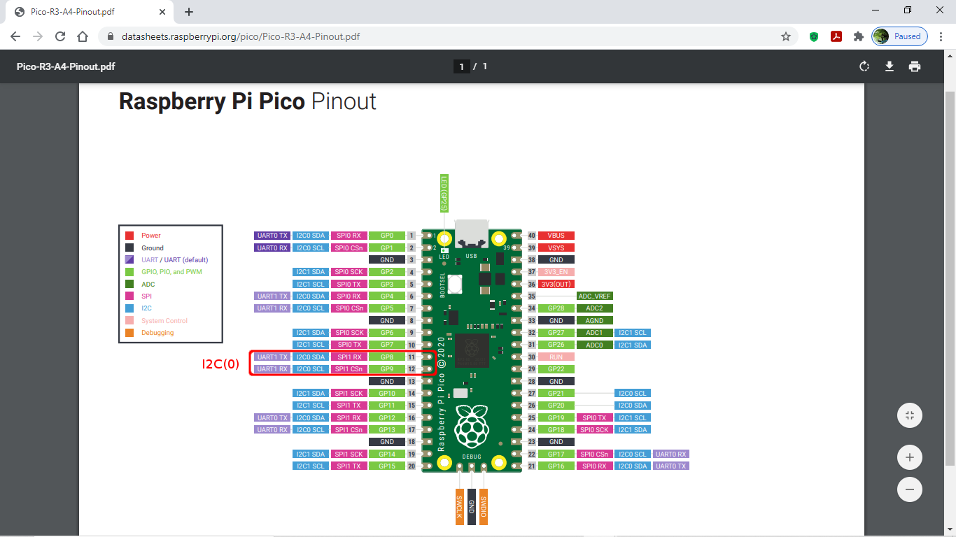
Connection:
I'm going to use the default pin assignment of SPI(0), enter the code in MicroPython REPL:
>>> import machine
>>> print(machine.SPI(0))
>>> print(machine.SPI(1))
Assign TFT pins as:


Example code:
mpyPico_ili9341.py
"""
Exercise on Raspberry Pi Pico/MicroPython
with 320x240 ILI9341 SPI Display
"""
from ili934xnew import ILI9341, color565
from machine import Pin, SPI
from micropython import const
import os
import glcdfont
import tt14
import tt24
import tt32
import time
SCR_WIDTH = const(320)
SCR_HEIGHT = const(240)
SCR_ROT = const(2)
CENTER_Y = int(SCR_WIDTH/2)
CENTER_X = int(SCR_HEIGHT/2)
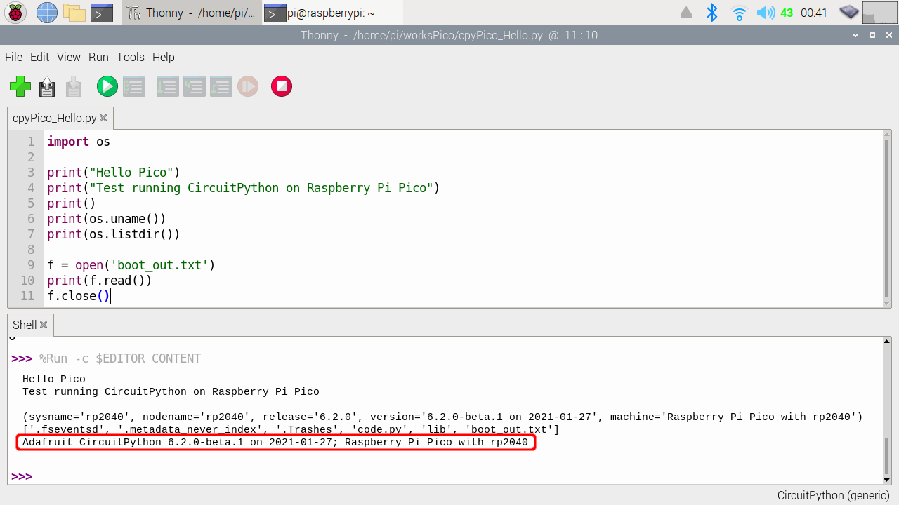
print(os.uname())
TFT_CLK_PIN = const(6)
TFT_MOSI_PIN = const(7)
TFT_MISO_PIN = const(4)
TFT_CS_PIN = const(13)
TFT_RST_PIN = const(14)
TFT_DC_PIN = const(15)
fonts = [glcdfont,tt14,tt24,tt32]
text = 'Hello Raspberry Pi Pico/ili9341'
print(text)
print("fonts available:")
for f in fonts:
print(f.__name__)
spi = SPI(
0,
baudrate=40000000,
miso=Pin(TFT_MISO_PIN),
mosi=Pin(TFT_MOSI_PIN),
sck=Pin(TFT_CLK_PIN))
print(spi)
display = ILI9341(
spi,
cs=Pin(TFT_CS_PIN),
dc=Pin(TFT_DC_PIN),
rst=Pin(TFT_RST_PIN),
w=SCR_WIDTH,
h=SCR_HEIGHT,
r=SCR_ROT)
display.erase()
display.set_pos(0,0)
for ff in fonts:
display.set_font(ff)
display.print(text)
display.set_font(tt24)
display.set_color(color565(255, 255, 0), color565(150, 150, 150))
display.print("\nThanks:")
display.print("https://github.com/jeffmer/micropython-ili9341")
time.sleep(1)
for i in range(170):
display.scroll(1)
time.sleep(0.01)
time.sleep(1)
for i in range(170):
display.scroll(-1)
time.sleep(0.01)
time.sleep(1)
for h in range(SCR_WIDTH):
if h > SCR_HEIGHT:
w = SCR_HEIGHT
else:
w = h
display.fill_rectangle(0, 0, w, h, color565(0, 0, 255))
time.sleep(0.01)
time.sleep(0.5)
display.erase()
# Helper function to draw a circle from a given position with a given radius
# This is an implementation of the midpoint circle algorithm,
# see https://en.wikipedia.org/wiki/Midpoint_circle_algorithm#C_example
# for details
def draw_circle(xpos0, ypos0, rad, col=color565(255, 255, 255)):
x = rad - 1
y = 0
dx = 1
dy = 1
err = dx - (rad << 1)
while x >= y:
display.pixel(xpos0 + x, ypos0 + y, col)
display.pixel(xpos0 + y, ypos0 + x, col)
display.pixel(xpos0 - y, ypos0 + x, col)
display.pixel(xpos0 - x, ypos0 + y, col)
display.pixel(xpos0 - x, ypos0 - y, col)
display.pixel(xpos0 - y, ypos0 - x, col)
display.pixel(xpos0 + y, ypos0 - x, col)
display.pixel(xpos0 + x, ypos0 - y, col)
if err <= 0:
y += 1
err += dy
dy += 2
if err > 0:
x -= 1
dx += 2
err += dx - (rad << 1)
draw_circle(CENTER_X, CENTER_Y, 100)
display.set_pos(1,10)
display.print("helloraspberrypi.blogspot.com")
for c in range(99):
draw_circle(CENTER_X, CENTER_Y, c, color565(255, 0, 0))
for c in range(98):
draw_circle(CENTER_X, CENTER_Y, c, color565(0, 255, 0))
for c in range(97):
draw_circle(CENTER_X, CENTER_Y, c, color565(0, 0, 255))
print("- bye-")
Updated@2021-02-27:

It's a utility font_to_py.py in the project, used to convert ttf to py can
be used in this library.
This video show how I convery FreeSans font to py, and use on RPi
Pico/MicroPython + ili9341 exercises.
Convert .ttf to .py
- visit
jeffmer/micropython-ili9341 and download font_to_py.py.
Sample usage:
font_to_py.py FreeSans.ttf 23 freesans.py
To specify monospaced rendering issue:
font_to_py.py FreeSans.ttf 23 --fixed freesans.py
- search and download ttf from internet, FreeSans.ttf as a example.
-
opensourcedesign/fonts
found.
- run font_to_py.py to convert font:
> python3 font_to_py.py FreeSans.ttf 48 freesans48.py
most possible you fail with error:
ModuleNotFoundError: No module named 'freetype'
- To install freetype, enter the command:
> pip3 install freetype.py
- run font_to_py.py to convert font again:
python3 font_to_py.py FreeSans.ttf 48 freesans48.py
and:
python3 font_to_py.py FreeSans.ttf 48 --fixed freesans48fixed.py
- copy freesans48.py and freesans48fixed.py to Raspberry Pi Pico
Done. you can try freesans48.py and freesans48fixed.py using my example
MicroPython code on Raspberry Pi Pico.
"""
Exercise on Raspberry Pi Pico/MicroPython
with 320x240 ILI9341 SPI Display
"""
from ili934xnew import ILI9341, color565
from machine import Pin, SPI
from micropython import const
import os
import glcdfont
import tt14
import tt24
import tt32
import utime

import freesans48
import freesans48fixed

SCR_WIDTH = const(320)
SCR_HEIGHT = const(240)
SCR_ROT = const(1)   #const(2)
CENTER_Y = int(SCR_WIDTH/2)
CENTER_X = int(SCR_HEIGHT/2)

print(os.uname())
TFT_CLK_PIN = const(6)
TFT_MOSI_PIN = const(7)
TFT_MISO_PIN = const(4)

TFT_CS_PIN = const(13)
TFT_RST_PIN = const(14)
TFT_DC_PIN = const(15)


spi = SPI(
    0,
    baudrate=40000000,
    miso=Pin(TFT_MISO_PIN),
    mosi=Pin(TFT_MOSI_PIN),
    sck=Pin(TFT_CLK_PIN))
print(spi)

display = ILI9341(
    spi,
    cs=Pin(TFT_CS_PIN),
    dc=Pin(TFT_DC_PIN),
    rst=Pin(TFT_RST_PIN),
    w=SCR_WIDTH,
    h=SCR_HEIGHT,
    r=SCR_ROT)

display.erase()
display.set_pos(0,0)

#demo freesans48
display.set_font(freesans48)
display.erase()
display.set_pos(0,0)
display.print("freesans48")
display.print("1234567890")
utime.sleep(1)

display.erase()
display.set_pos(0,0)
display.print("ABCDEFGHIJKLMNOPQRST")
utime.sleep(1)
display.erase()
display.set_pos(0,0)
display.print("UVWXYZ")
utime.sleep(1)
display.erase()
display.set_pos(0,0)
display.print("abcdefghijklmno")
utime.sleep(1)
display.erase()
display.set_pos(0,0)
display.print("pqrstuvwxyz")
utime.sleep(1)

#demo freesans48fixed
display.erase()
display.set_pos(0,0)

display.set_font(freesans48fixed)

display.print("freesans48fixed")

utime.sleep(1)


for i in range(130):
    display.scroll(1)
    utime.sleep(0.01)
utime.sleep(1)
for i in range(130):
    display.scroll(-1)
    utime.sleep(0.01)
utime.sleep(1)


display.erase()
display.set_pos(0,0)
display.print("ABCDEFGHIJKLMNOPQ")
utime.sleep(1)
display.erase()
display.set_pos(0,0)
display.print("RSTUVWXYZ")
utime.sleep(1)
display.erase()
display.set_pos(0,0)
display.print("abcdefghijklmno")
utime.sleep(1)
display.erase()
display.set_pos(0,0)
display.print("pqrstuvwxyz")
utime.sleep(1)

display.erase()
display.set_pos(0,0)
display.print("1234567890")
utime.sleep(1)
display.erase()
display.set_pos(0,0)
display.print("!@#$%^&*()~_`-")
utime.sleep(1)
display.erase()
display.set_pos(0,0)
display.print("{}[]:;<>,.?/|")
utime.sleep(1)

print("- bye-")
next example of Raspberry Pico Pico/MicroPython + 320x240 ILI9341 SPI Display: