To make your Raspberry Pi enter bootloader mode, it's normally suggested hold down the BOOTSEL button while plugging the board into USB. Alternatively, you can hold down the BOOTSEL button and pull down the RUN/Reset pin.
It's third software approach to enter bootloader mode: run machine.bootloader() at the MicroPython REPL.
It's assumed you have already installed MicroPython firmware on your Raspberry Pi Pico.
Run in MicroPython:
>>> import machine
>>> machine.bootloader()
Your RPi Pico will appear as a USB disk drive you can drag the firmware onto.
In this exercise, - the ESP32 web server code is modified to replace the
role of Raspberry Pi/Python Server. Setup as WiFi Access Point, run a socket
server on port 9999, wait connection from client, receive data, convert to
upper case and echo back. - RPi Pico+ESP-01S join the ESP32 WiFi network,
connect to 192.168.4.1 (the default IP of ESP32 SoftAP), port 9999, send data
and wait response.
Both coded in MicroPython.
In my practice as shown in the video, a Raspberry Pi 4B is used as development host for both ESP32
and Pico using MicroPython. Firstly, in Thonny, save server code
(upyESP32_AP_EchoSvr_20210224a.py) on ESP32, name main.py. Switch Thonny
interpreter for Pico and port. Then open Putty as serial terminal connect to
ESP32 as REPL to monitor the output from ESP32. Finally, run the client code
(mpyPico_ESP-01S_TCPclient_20210224a.py) in Thonny.
upyESP32_AP_EchoSvr_20210224a.py, run on ESP32 as server.
import uos
import network
import usocket
"""
ESP32/MicroPython exercise:
ESP32 act as Access Point,
and setup a simple TCP echo server

ref:
MicroPython usocket – socket module
https://docs.micropython.org/en/latest/library/usocket.html
"""

ssid= "ESP32-ssid"
password="password"

print("----- MicroPython -----")
for u in uos.uname():
    print(u)
print("-----------------------")

ap = network.WLAN(network.AP_IF) # Access Point
ap.config(essid=ssid,
          password=password,
          authmode=network.AUTH_WPA_WPA2_PSK)
ap.config(max_clients=1)  # max number of client
ap.active(True)           # activate the access point

print(ap.ifconfig())
print(dir(ap))

mysocket = usocket.socket(usocket.AF_INET, usocket.SOCK_STREAM)
mysocket.setsockopt(usocket.SOL_SOCKET, usocket.SO_REUSEADDR, 1)

mysocket.bind(('', 9999))
mysocket.listen(1)

while True:
  conn, addr = mysocket.accept()
  print('Connected from: %s' % str(addr))
  print()
  request = conn.recv(1024)
  print('request: %s' % str(request))
  print()
  conn.send(request.upper())
  conn.send('\r\n')
  conn.close()
mpyPico_ESP-01S_TCPclient_20210224a.py, run on Raspberry Pi Pico, as
client.
import uos
import machine
import utime
"""
Raspberry Pi Pico/MicroPython + ESP-01S exercise

ESP-01S(ESP8266) with AT-command firmware:
AT version:1.7.4.0(May 11 2020 19:13:04)

Pico send AT command to ESP-01S via UART,
- set in station mode
- join AP
- connect to server ip:port 9999
- send text and wait response
"""
#server port & ip hard-coded,
#have to match with server side setting
server_ip="192.168.4.1"
server_port=9999

print()
print("Machine: \t" + uos.uname()[4])
print("MicroPython: \t" + uos.uname()[3])

#indicate program started visually
led_onboard = machine.Pin(25, machine.Pin.OUT)
led_onboard.value(0)     # onboard LED OFF/ON for 0.5/1.0 sec
utime.sleep(0.5)
led_onboard.value(1)
utime.sleep(1.0)
led_onboard.value(0)

uart0 = machine.UART(0, baudrate=115200)
print(uart0)

def sendCMD_waitResp(cmd, uart=uart0, timeout=2000):
    print("CMD: " + cmd)
    uart.write(cmd)
    waitResp(uart, timeout)
    print()

def waitResp(uart=uart0, timeout=2000):
    prvMills = utime.ticks_ms()
    resp = b""
    while (utime.ticks_ms()-prvMills)<timeout:
        if uart.any():
            resp = b"".join([resp, uart.read(1)])
    print("resp:")
    try:
        print(resp.decode())
    except UnicodeError:
        print(resp)

# send CMD to uart,
# wait and show response without return
def sendCMD_waitAndShow(cmd, uart=uart0):
    print("CMD: " + cmd)
    uart.write(cmd)
    while True:
        print(uart.readline())

def espSend(text="test", uart=uart0):
    sendCMD_waitResp('AT+CIPSEND=' + str(len(text)) + '\r\n')
    sendCMD_waitResp(text)

def XmonitorESP(uart=uart0):
    """
    while True:
        line=uart.readline()
        try:
            print(line.decode())
        except UnicodeError:
            print(line)
    """
    while True:
        if uart.any():
            print(uart.read(1))

sendCMD_waitResp('AT\r\n')          #Test AT startup
sendCMD_waitResp('AT+GMR\r\n')      #Check version information
#sendCMD_waitResp('AT+RESTORE\r\n')  #Restore Factory Default Settings

sendCMD_waitResp('AT+CWMODE?\r\n')  #Query the Wi-Fi mode
sendCMD_waitResp('AT+CWMODE=1\r\n') #Set the Wi-Fi mode 1 = Station mode
#sendCMD_waitResp('AT+CWMODE=2\r\n') #Set the Wi-Fi mode 2 = S0ftAP mode
sendCMD_waitResp('AT+CWMODE?\r\n')  #Query the Wi-Fi mode again

#sendCMD_waitResp('AT+CWLAP\r\n', timeout=10000) #List available APs
sendCMD_waitResp('AT+CWJAP="ESP32-ssid","password"\r\n', timeout=5000) #Connect to AP
sendCMD_waitResp('AT+CIFSR\r\n')    #Obtain the Local IP Address
#sendCMD_waitResp('AT+CIPSTART="TCP","192.168.12.147",9999\r\n')
sendCMD_waitResp('AT+CIPSTART="TCP","' +
                 server_ip +
                 '",' +
                 str(server_port) +
                 '\r\n')
espSend()

while True:
    print('Enter something:')
    msg = input()
    #sendCMD_waitResp('AT+CIPSTART="TCP","192.168.12.147",9999\r\n')
    sendCMD_waitResp('AT+CIPSTART="TCP","' +
                 server_ip +
                 '",' +
                 str(server_port) +
                 '\r\n')
    espSend(msg)
Without this code, error of "OSError: [Errno 98] EADDRINUSE" will be thrown sometimes; such as Run the program > client connect and load the web page > then re-start the program.
Steps to install MicroPython firmware on ESP32 (ESP32-DevKitC V4, with
ESP32-WROVER-E) using Thonny Python IDE, on Raspberry Pi/Raspberry Pi
OS(32-bit). Include install esptool plug-ins.
Visit
http://micropython.org/download/, scroll down to select Generic ESP32 module. Download firmware (.bin)
using either ESP-IDF v3.x or v4.x.
There are various daily firmware for ESP32-based boards, with separate firmware for boards with and without external SPIRAM, using either ESP-IDF v3.x or v4.x.
Non-SPIRAM firmware will work on any board, whereas SPIRAM enabled firmware will only work on boards with 4MiB of external pSRAM.
And currently, Firmware built with ESP-IDF v4.x, with support for BLE and PPP, but no LAN. Firmware built with ESP-IDF v3.x, with support for BLE, LAN and PPP. MicroPython v1.14 was the last version to support ESP-IDF v3.x.
If in doubt use v4.x.
Run Thonny
Run in Raspberry Pi OS Start Menu: > programming > Thonny Python
IDE
Install esptool plus-ins:
In Thonny menu: > Tools > Manager plug-ins... Search and
install esptool
Install MicroPython firmware:
In Thonny menu: > Run > Select Interpreter...
Select MicroPython (ESP32) from the interpreter or device drop-down box. Click
Install or Update firmware.
Select the USB port connected to ESP32. Browse to load firmware. Click
Install.
Once Done, MicroPython installed on ESP32.
Example:
upyESP32_scan.py, example to scan available WiFi networks.
import uos
import network

print("----- MicroPython -----")
for u in uos.uname():
    print(u)
print("-----------------------")

sta_if = network.WLAN(network.STA_IF)
print(sta_if)
sta_if.active(True)
for ap in sta_if.scan():
    print(ap)
upyESP32_connect.py, example to connect WiFi network.
import uos
import network

print("----- MicroPython -----")
for u in uos.uname():
    print(u)
print("-----------------------")

def do_connect():
    sta_if = network.WLAN(network.STA_IF)
    if not sta_if.isconnected():
        print('connecting to network...')
        sta_if.active(True)
        sta_if.connect('ssid', 'password')
        while not sta_if.isconnected():
            pass
    print('network config:', sta_if.ifconfig())

do_connect()
The TCP server side is implemented using Python3 socketserver. It's copied and modified from Python Document > socketserver.
Both TCP server and client have to be connected in the same WiFi network.
mpyPico_ESP-01S_TCPclient_2021-02-21a.py, client side run on Raspberry Pi Pico, programmed in MicroPython.
import uos
import machine
import utime
"""
Raspberry Pi Pico/MicroPython + ESP-01S exercise
ESP-01S(ESP8266) with AT-command firmware:
AT version:1.7.4.0(May 11 2020 19:13:04)
Pico send AT command to ESP-01S via UART,
- set in station mode
- join AP
- connect to server ip:port 9999
- send text and wait response
"""
#server port & ip hard-coded,
#have to match with server side setting
server_ip="192.168.12.147"
server_port=9999
print()
print("Machine: \t" + uos.uname()[4])
print("MicroPython: \t" + uos.uname()[3])
#indicate program started visually
led_onboard = machine.Pin(25, machine.Pin.OUT)
led_onboard.value(0) # onboard LED OFF/ON for 0.5/1.0 sec
utime.sleep(0.5)
led_onboard.value(1)
utime.sleep(1.0)
led_onboard.value(0)
uart0 = machine.UART(0, baudrate=115200)
print(uart0)
def sendCMD_waitResp(cmd, uart=uart0, timeout=2000):
print("CMD: " + cmd)
uart.write(cmd)
waitResp(uart, timeout)
print()
def waitResp(uart=uart0, timeout=2000):
prvMills = utime.ticks_ms()
resp = b""
while (utime.ticks_ms()-prvMills)<timeout:
if uart.any():
resp = b"".join([resp, uart.read(1)])
print("resp:")
try:
print(resp.decode())
except UnicodeError:
print(resp)
# send CMD to uart,
# wait and show response without return
def sendCMD_waitAndShow(cmd, uart=uart0):
print("CMD: " + cmd)
uart.write(cmd)
while True:
print(uart.readline())
def espSend(text="test", uart=uart0):
sendCMD_waitResp('AT+CIPSEND=' + str(len(text)) + '\r\n')
sendCMD_waitResp(text)
sendCMD_waitResp('AT\r\n') #Test AT startup
sendCMD_waitResp('AT+GMR\r\n') #Check version information
#sendCMD_waitResp('AT+RESTORE\r\n') #Restore Factory Default Settings
sendCMD_waitResp('AT+CWMODE?\r\n') #Query the Wi-Fi mode
sendCMD_waitResp('AT+CWMODE=1\r\n') #Set the Wi-Fi mode 1 = Station mode
#sendCMD_waitResp('AT+CWMODE=2\r\n') #Set the Wi-Fi mode 2 = S0ftAP mode
sendCMD_waitResp('AT+CWMODE?\r\n') #Query the Wi-Fi mode again
#sendCMD_waitResp('AT+CWLAP\r\n', timeout=10000) #List available APs
sendCMD_waitResp('AT+CWJAP="ssid","password"\r\n', timeout=5000) #Connect to AP
sendCMD_waitResp('AT+CIFSR\r\n') #Obtain the Local IP Address
#sendCMD_waitResp('AT+CIPSTART="TCP","192.168.12.147",9999\r\n')
sendCMD_waitResp('AT+CIPSTART="TCP","' +
server_ip +
'",' +
str(server_port) +
'\r\n')
espSend()
while True:
print('Enter something:')
msg = input()
#sendCMD_waitResp('AT+CIPSTART="TCP","192.168.12.147",9999\r\n')
sendCMD_waitResp('AT+CIPSTART="TCP","' +
server_ip +
'",' +
str(server_port) +
'\r\n')
espSend(msg)
pyMyTCPServer_2021-02-21a.py, run on Raspberry Pi, programmed in Python.
"""
ref:
https://docs.python.org/3/library/socketserver.html
"""
import socketserver
import platform
print("sys info:")
for info in platform.uname():
print(info)
class MyTCPHandler(socketserver.BaseRequestHandler):
"""
The request handler class for our server.
It is instantiated once per connection to the server, and must
override the handle() method to implement communication to the
client.
"""
def handle(self):
# self.request is the TCP socket connected to the client
self.data = self.request.recv(1024).strip()
print("{} wrote:".format(self.client_address[0]))
print(self.data)
# just send back the same data, but upper-cased
self.request.sendall(self.client_address[0].encode())
self.request.sendall(self.data.upper())
self.request.sendall(b'\r\n')
if __name__ == "__main__":
HOST, PORT = "localhost", 9999
# Create the server, binding to localhost on port 9999
#with socketserver.TCPServer((HOST, PORT), MyTCPHandler) as server:
with socketserver.TCPServer(('', PORT), MyTCPHandler) as server:
# Activate the server; this will keep running until you
# interrupt the program with Ctrl-C
server.serve_forever()
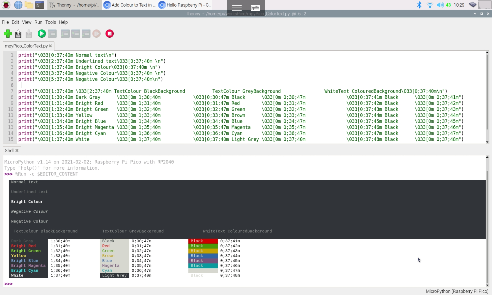
Found a simple approach to print() text in color for Python REPL:
To make some of your text more readable, you can use ANSI escape codes to change the colour of the text output in your python program. A good use case for this is to to highlight errors. ~ read here: ozzmaker - Add Colour to Text in Python
Test on Raspberry Pi/Thonny with interpreter of MicroPython on Raspberry Pi Pico:
Just first connect ESP-01S to Raspberry Pi Pico/MicroPython UART, send
AT-Command, set in Station Mode, connect to AP.
Connection:
Exercise code (MicroPython):
mpyPico_ESP-01S_20210219a.py
import uos
import machine
import utime
"""
ESPRESSIF AT Command Set
https://docs.espressif.com/projects/esp-at/en/latest/AT_Command_Set/
"""
print()
print("Machine: \t" + uos.uname()[4])
print("MicroPython: \t" + uos.uname()[3])
#indicate program started visually
led_onboard = machine.Pin(25, machine.Pin.OUT)
led_onboard.value(0) # onboard LED OFF/ON for 0.5/1.0 sec
utime.sleep(0.5)
led_onboard.value(1)
utime.sleep(1.0)
led_onboard.value(0)
uart0 = machine.UART(0, baudrate=115200)
print(uart0)
def sendCMD_waitResp(cmd, uart=uart0, timeout=2000):
print("CMD: " + cmd)
uart.write(cmd)
waitResp(uart, timeout)
print()
def waitResp(uart=uart0, timeout=2000):
prvMills = utime.ticks_ms()
resp = b""
while (utime.ticks_ms()-prvMills)<timeout:
if uart.any():
resp = b"".join([resp, uart.read(1)])
print("resp:")
try:
print(resp.decode())
except UnicodeError:
print(resp)
sendCMD_waitResp('AT\r\n') #Test AT startup
sendCMD_waitResp('AT+GMR\r\n') #Check version information
#sendCMD_waitResp('AT+RESTORE\r\n') #Restore Factory Default Settings
sendCMD_waitResp('AT+CWMODE?\r\n') #Query the Wi-Fi mode
sendCMD_waitResp('AT+CWMODE=1\r\n') #Set the Wi-Fi mode = Station mode
sendCMD_waitResp('AT+CWMODE?\r\n') #Query the Wi-Fi mode again
#sendCMD_waitResp('AT+CWLAP\r\n', timeout=10000) #List available APs
sendCMD_waitResp('AT+CWJAP="ssid","password"\r\n', timeout=5000) #Connect to AP
sendCMD_waitResp('AT+CIFSR\r\n') #Obtain the Local IP Address
output in REPL:
MicroPython v1.14 on 2021-02-02; Raspberry Pi Pico with RP2040
Type "help()" for more information.
>>> %Run -c $EDITOR_CONTENT
Machine: Raspberry Pi Pico with RP2040
MicroPython: v1.14 on 2021-02-02 (GNU 9.3.0 MinSizeRel)
UART(0, baudrate=115200, bits=8, parity=None, stop=1, tx=0, rx=1)
CMD: AT
resp:
AT
OK
CMD: AT+GMR
resp:
AT+GMR
AT version:1.7.4.0(May 11 2020 19:13:04)
SDK version:3.0.4(9532ceb)
compile time:May 27 2020 10:12:17
Bin version(Wroom 02):1.7.4
OK
CMD: AT+CWMODE?
resp:
AT+CWMODE?
+CWMODE:1
OK
CMD: AT+CWMODE=1
resp:
AT+CWMODE=1
OK
CMD: AT+CWMODE?
resp:
AT+CWMODE?
+CWMODE:1
OK
CMD: AT+CWJAP="ssid","password"
resp:
AT+CWJAP="ssid","password"
WIFI DISCONNECT
WIFI CONNECTED
WIFI GOT IP
OK
CMD: AT+CIFSR
resp:
AT+CIFSR
+CIFSR:STAIP,"192.168.221.249"
+CIFSR:STAMAC,"e0:98:06:24:b3:a4"
OK
>>>
It's a exercise for Raspberry Pi Pico running CircuitPython 6.2.0-beta.2, to read AHT20+BMP280 Temperature, Humidity and Pressure Sensor Module, and display on SSD1306 I2C OLED.
AHT20+BMP280 Digital Temperature, Humidity and Pressure Sensor Module
It's a module adopts the digital temperature and humidity sensor AHT20 and Bosch BPM280 composed of Aosong, I2C mainstream output,
Connection:
In this exercise, both the I2C from AHT20+BMP280 module and from SSD1306 OLED connect to one common I2C port of Raspberry Pi Pico.
Driver libraries:
Visit https://circuitpython.org/libraries, download the appropriate bundle for your version of CircuitPython. Unzip the file, and copy the needed file/directory to /lib directory of your Raspberry Pi Pico CIRCUITPY driver.
If you looking for read the sensor module only, only adafruit_ahtx0.mpy and adafruit_bmp280.mpy are needed. adafruit_displayio_ssd1306.mpy, adafruit_display_shapes and adafruit_display_text directories are needed for ssd1306 I2C OLED.
cpyPico_bmp280_simpletest.py, read BMP280 sensor. Basically it is modifed from the bmp280_simpletest.py example come with the downloaed Adafruit CircuitPython Library, with change of GPIO for I2C only.
# SPDX-FileCopyrightText: 2021 ladyada for Adafruit Industries
# SPDX-License-Identifier: MIT

"""Simpletest Example that shows how to get temperature,
   pressure, and altitude readings from a BMP280"""
import time
import board

# import digitalio # For use with SPI
import busio
import adafruit_bmp280

# Create library object using our Bus I2C port
#i2c = busio.I2C(board.SCL, board.SDA)
SDA = board.GP8
SCL = board.GP9
i2c = busio.I2C(SCL, SDA)
bmp280 = adafruit_bmp280.Adafruit_BMP280_I2C(i2c)

# OR create library object using our Bus SPI port
# spi = busio.SPI(board.SCK, board.MOSI, board.MISO)
# bmp_cs = digitalio.DigitalInOut(board.D10)
# bmp280 = adafruit_bmp280.Adafruit_BMP280_SPI(spi, bmp_cs)

# change this to match the location's pressure (hPa) at sea level
bmp280.sea_level_pressure = 1013.25

while True:
    print("\nTemperature: %0.1f C" % bmp280.temperature)
    print("Pressure: %0.1f hPa" % bmp280.pressure)
    print("Altitude = %0.2f meters" % bmp280.altitude)
    time.sleep(2)
cpyPico_ahtx0_simpletest.py, read AHT20 sensor, modify from ahtx0_simpletest.py example.
# SPDX-FileCopyrightText: 2021 ladyada for Adafruit Industries
# SPDX-License-Identifier: MIT

import time
import board
import adafruit_ahtx0
import busio

# Create the sensor object using I2C
SDA = board.GP8
SCL = board.GP9
i2c = busio.I2C(SCL, SDA)
sensor = adafruit_ahtx0.AHTx0(i2c)
#sensor = adafruit_ahtx0.AHTx0(board.I2C())

while True:
    print("\nTemperature: %0.1f C" % sensor.temperature)
    print("Humidity: %0.1f %%" % sensor.relative_humidity)
    time.sleep(2)
cpyPico_bmp280_ssd1306.py, read BMP280 sensor, display on ssd1306 I2C OLED.
This example run on Raspberry Pi Pico/CircuitPython, to display on 128x64 I2C OLED Display using adafruit_displayio_ssd1306 driver.
It's assumed the CircuitPython is installed on Raspberry Pi Pico, current CircuitPython 6.2.0-beta.2 is installed in this exercise. Refer to the post to "Install CircuitPython firmware on Raspberry Pi Pico".
Library:
In this exercise, adafruit_displayio_ssd1306 and adafruit_display_text of Adafruit CircuitPython Library Bundle is needed.
Unzip the file, copy adafruit_displayio_ssd1306.mpy and adafruit_display_text folder to the lib folder on your CIRCUITPY drive.
Connection:
Example code:
cpyPico-ssd1306-displayio-20210216a.py
import os
import time
import busio
import board
import displayio
import terminalio
import adafruit_displayio_ssd1306
from adafruit_display_text import label

WIDTH = 128
HEIGHT = 64
CENTER_X = int(WIDTH/2)
CENTER_Y = int(HEIGHT/2)

displayio.release_displays()

SDA = board.GP8
SCL = board.GP9
i2c = busio.I2C(SCL, SDA)

if(i2c.try_lock()):
    print("i2c.scan(): " + str(i2c.scan()))
    i2c.unlock()
print()

display_bus = displayio.I2CDisplay(i2c, device_address=60)
display = adafruit_displayio_ssd1306.SSD1306(display_bus, width=128, height=64)
"""
“displayio” drivers will also work with CircuitPython to display error messages
and other output to the display when the user code is not using it.
"""
print("Raspberry Pi Pico/CircuitPython ")
print("SSD1306 displayio (adafruit_displayio_ssd1306)")
time.sleep(0.5)

print()
print("os.uname():")
uname = os.uname()
for u in uname:
    print(u)
    time.sleep(1)

print()
print(adafruit_displayio_ssd1306.__name__ + " : " + adafruit_displayio_ssd1306.__version__)
print()
#================================================
# Make the display context
group = displayio.Group(max_size=10)

NUM_OF_COLOR = 2
bitmap = displayio.Bitmap(WIDTH, HEIGHT, NUM_OF_COLOR)
bitmap_palette = displayio.Palette(NUM_OF_COLOR)
bitmap_palette[0] = 0x000000
bitmap_palette[1] = 0xFFFFFF

tileGrid = displayio.TileGrid(bitmap,
                              pixel_shader=bitmap_palette,
                              x=0, y=0)
group.append(tileGrid)
display.show(group)

"""
print("bitmap: ")
print(type(bitmap))
print(dir(bitmap))
print("bitmap_palette")
print(type(bitmap_palette))
print(dir(bitmap_palette))
print("tileGrid")
print(type(tileGrid))
print(dir(tileGrid))
print("group")
print(type(group))
print(dir(group))
print("display")
print(type(display))
print(dir(display))
"""

time.sleep(1)
bitmap.fill(1)

def range_f(start, stop, step):
    f = start
    while f < stop:
        yield f
        f += step

time.sleep(1)
for y in range_f(0, HEIGHT-1, 2):
    for x in range_f(0, WIDTH-1, 2):
        #print(str(x) + " : " + str(y))
        bitmap[x, y] = 0

time.sleep(1)
#========================================================
# Draw a label
text_group1 = displayio.Group(max_size=10, scale=3, x=0, y=0)
text1 = "Hello"
text_area1 = label.Label(terminalio.FONT, text=text1, color=0xFFFFFF)
text_group1.append(text_area1)
group.append(text_group1)

"""
print("text_group1:")
print(type(text_group1))
print(dir(text_group1))
"""

for xy in range(20):
    time.sleep(0.1)
    text_group1.x=xy
    text_group1.y=xy
#========================================================
#invert palette
time.sleep(1)
bitmap_palette[1] = 0x000000
bitmap_palette[0] = 0xFFFFFF

time.sleep(1)
y = 0
for x in range_f(0, WIDTH-1, 1):
    bitmap[x, y] = 0
    time.sleep(0.01)
x = WIDTH-1
for y in range_f(0, HEIGHT-1, 1):
    bitmap[x, y] = 0
    time.sleep(0.01)

y = HEIGHT-1
for x in range_f(0, WIDTH-1, 1):
    bitmap[x, y] = 0
    time.sleep(0.01)
x = 0
for y in range_f(0, HEIGHT-1, 1):
    bitmap[x, y] = 0
    time.sleep(0.01)

#invert palette
time.sleep(1)
bitmap_palette[0] = 0x000000
bitmap_palette[1] = 0xFFFFFF
#invert palette
time.sleep(1)
bitmap_palette[1] = 0x000000
bitmap_palette[0] = 0xFFFFFF

time.sleep(1)
bitmap.fill(1)
time.sleep(1)
for xy in range(20):
    time.sleep(0.1)
    text_group1.x=xy+20
    text_group1.y=xy+20
time.sleep(1)
print("- bye -")
Next:
~ RPi Pico/CircuitPython x AHT20+BMP280 (Temperature, Humidity and Pressure Sensor Module), display on ssd1306 I2C OLED
In the display drivers of CircuitPython libraries: Pixel based displays are implemented in two different ways. The original method called “framebuf” uses a traditional frame buffer model where all pixels are stored in the microcontroller’s ram. The newer method called “displayio” generates the pixels on the fly and relies on the display’s ram to store the final pixels. “displayio” drivers will also work with CircuitPython to display error messages and other output to the display when the user code is not using it.
The library used in this exercise adafruit_displayio_ssd1306 is displayio library for ssd1306.
Releasing Displays:
Once you've created your display instance, the CircuitPython firmware will remember the setup between soft resets. This helps facilitate showing the serial output on the display, which can be useful for seeing error messages, etc.. Because of this behavior, you may run into error issue.
To avoid this issue, you can use the release_displays() command in displayio. Call this before creating your display bus.
Please notice that the default BAUD (after AT+ORGL command) is 38400. Most factory preset it 9600 baud in order to make it compatible with HC-06. In this exercise, it's reset to 38400.
The test program is same as in last exercise, except baud rate = 38400.
mpyPico_comm_38400_20210210a.py
import uos
import machine
import utime

"""
Raspberry Pi Pico/MicroPython to test bluetooth/Sertal
bi-direction commnunication between HC-05/HC-06

default UART
UART(0, baudrate=9600, bits=8, parity=None, stop=1, tx=0, rx=1)
UART(1, baudrate=115200, bits=8, parity=None, stop=1, tx=4, rx=5)

both set to 9600 baud

Connection:
RPi Pico UART0  HC-05/06
GP0(pin 1)      RX
GP1(pin 2)      TX

RPi Pico UART1  HC-05/06
GP4(pin 6)      RX
GP5(pin 7)      TX

To enter normal mode:
HC-05:
Just power on WITHOUT pressing the onboard button
HC-06:
Just power on

"""

print(uos.uname())
uart0 = machine.UART(0,baudrate=38400)
uart1 = machine.UART(1,baudrate=38400)

def clartBuf(uart=uart0):
    print("Clear UART buffer "+ str(uart))
    while uart.any():
        print(uart.read(1))

#indicate program started visually
led_onboard = machine.Pin(25, machine.Pin.OUT)
led_onboard.value(0)     # onboard LED OFF/ON for 0.5/1.0 sec
utime.sleep(0.5)
led_onboard.value(1)
utime.sleep(1.0)
led_onboard.value(0)

print(uart0)
print(uart1)

clartBuf()
clartBuf(uart1)

#Master HC-05 send a dummy bytes in lower case
uart1.write("1234567890abcdefghijklmnopqrstuvwxyz\r\n")

#Slave HC-05 convert received bytes to upper case, and echo back.
#if you see in REPL a byte in lower case, it is send from Master to Slave,
#in upper case, it is echo back from Slave to Master.
prvMills = utime.ticks_ms()
bUart0 = b''
bUart1 = b''
while (utime.ticks_ms()-prvMills)<3000:
    if uart0.any():
        b0 = uart0.read(1)
        bUart0 = bUart0 + b0
        print("UART(0): " + b0.decode('utf-8'))
        uart0.write(b0.upper().decode('utf-8'))
    if uart1.any():
        b1 = uart1.read(1)
        bUart1 = bUart1 + b1
        print("UART(1): " + b1.decode('utf-8'))

print("UART0: ")
print(bUart0)
print("UART1: ")
print(bUart1)

print("===========")
if bUart0 == bUart1.lower():
    print("MATCH")
else:
    print("UN-MATCH!!!")
print("===========")

print("- Done -")
In the above code, CMODE is 1, connect any address. Such that the master will connect to any HC-05 or HC-06 with matched PIN. If you want the master connect to a specified slave only, you can set CMODE=0, connect fix address. and bind the slave address to master using AT+BIND= command.
This exercise run MicroPython on Raspberry Pi Pico, program to pair HC-05 (connected to UART 0) and HC-06 (connected to UART 1). Then run a simple test program to verify.
Please note HC-05 and HC-06 are aged products and have many variants. My test is base on my modules bought at about 2015/16. It may be not same as yours.
Power off and on HC-05 in normal mode. It will connect to paired HC-06 automatically.
Run this code to verify, mpyPico_comm_9600_20210209a.py
import uos
import machine
import utime

"""
Raspberry Pi Pico/MicroPython to test bluetooth/Sertal
bi-direction commnunication between HC-05/HC-06

default UART
UART(0, baudrate=9600, bits=8, parity=None, stop=1, tx=0, rx=1)
UART(1, baudrate=115200, bits=8, parity=None, stop=1, tx=4, rx=5)

both set to 9600 baud

Connection:
RPi Pico UART0  HC-05/06
GP0(pin 1)      RX
GP1(pin 2)      TX

RPi Pico UART1  HC-05/06
GP4(pin 6)      RX
GP5(pin 7)      TX

To enter normal mode:
HC-05:
Just power on WITHOUT pressing the onboard button
HC-06:
Just power on

"""

print(uos.uname())
uart0 = machine.UART(0,baudrate=9600)
uart1 = machine.UART(1,baudrate=9600)

def clartBuf(uart=uart0):
    print("Clear UART buffer "+ str(uart))
    while uart.any():
        print(uart.read(1))

#indicate program started visually
led_onboard = machine.Pin(25, machine.Pin.OUT)
led_onboard.value(0)     # onboard LED OFF/ON for 0.5/1.0 sec
utime.sleep(0.5)
led_onboard.value(1)
utime.sleep(1.0)
led_onboard.value(0)

print(uart0)
print(uart1)

clartBuf()
clartBuf(uart1)

#Master HC-05 send a dummy bytes in lower case
uart1.write("1234567890abcdefghijklmnopqrstuvwxyz\r\n")

#Slave HC-05 convert received bytes to upper case, and echo back.
#if you see in REPL a byte in lower case, it is send from Master to Slave,
#in upper case, it is echo back from Slave to Master.
prvMills = utime.ticks_ms()
bUart0 = b''
bUart1 = b''
while (utime.ticks_ms()-prvMills)<3000:
    if uart0.any():
        b0 = uart0.read(1)
        bUart0 = bUart0 + b0
        print("UART(0): " + b0.decode('utf-8'))
        uart0.write(b0.upper().decode('utf-8'))
    if uart1.any():
        b1 = uart1.read(1)
        bUart1 = bUart1 + b1
        print("UART(1): " + b1.decode('utf-8'))

print("UART0: ")
print(bUart0)
print("UART1: ")
print(bUart1)

print("===========")
if bUart0 == bUart1.lower():
    print("MATCH")
else:
    print("UN-MATCH!!!")
print("===========")

print("- Done -")
REPL output:
>>> %Run -c $EDITOR_CONTENT
(sysname='rp2', nodename='rp2', release='1.14.0', version='v1.14 on 2021-02-02 (GNU 9.3.0 MinSizeRel)', machine='Raspberry Pi Pico with RP2040')
UART(0, baudrate=9600, bits=8, parity=None, stop=1, tx=0, rx=1)
UART(1, baudrate=9600, bits=8, parity=None, stop=1, tx=4, rx=5)
Clear UART buffer UART(0, baudrate=9600, bits=8, parity=None, stop=1, tx=0, rx=1)
Clear UART buffer UART(1, baudrate=9600, bits=8, parity=None, stop=1, tx=4, rx=5)
UART(0): 1
UART(0): 2
UART(0): 3
UART(0): 4
UART(1): 1
UART(0): 5
UART(1): 2
UART(0): 6
UART(1): 3
UART(0): 7
UART(1): 4
UART(0): 8
UART(1): 5
UART(0): 9
UART(1): 6
UART(0): 0
UART(1): 7
UART(0): a
UART(1): 8
UART(0): b
UART(1): 9
UART(0): c
UART(1): 0
UART(0): d
UART(1): A
UART(0): e
UART(1): B
UART(0): f
UART(1): C
UART(0): g
UART(1): D
UART(0): h
UART(1): E
UART(0): i
UART(1): F
UART(0): j
UART(1): G
UART(0): k
UART(1): H
UART(0): l
UART(1): I
UART(0): m
UART(1): J
UART(0): n
UART(1): K
UART(0): o
UART(1): L
UART(0): p
UART(1): M
UART(0): q
UART(1): N
UART(0): r
UART(1): O
UART(0): s
UART(1): P
UART(0): t
UART(1): Q
UART(0): u
UART(1): R
UART(0): v
UART(1): S
UART(0): w
UART(1): T
UART(0): x
UART(1): U
UART(0): y
UART(1): V
UART(0): z
UART(1): W
UART(0):
UART(1): X
UART(0):

UART(1): Y
UART(1): Z
UART(1):
UART(1):

UART0:
b'1234567890abcdefghijklmnopqrstuvwxyz\r\n'
UART1:
b'1234567890ABCDEFGHIJKLMNOPQRSTUVWXYZ\r\n'
===========
MATCH
===========
- Done -
In my test, have to edit st7789py.py littlle bit, otherwise it will be reported with error:
AttributeError: 'ST7789' object has no attribute 'xstart'
Edit st7789py.py, to add the line under def __init__():
	self.xstart = xstart
	self.ystart = ystart
Download fonts/vga2_8x8.py and vga1_16x32.py (or any font files you want) to Raspberry Pi Pico under new directory "fonts".
Example MicroPython for Raspberry Pi Pico, mpyPico_st7789.py:
"""
Raspberry Pi Pico/MicroPython exercise
240x240 ST7789 SPI LCD
using MicroPython library:
https://github.com/russhughes/st7789py_mpy

"""

import uos
import machine
import st7789py as st7789
from fonts import vga2_8x8 as font1
from fonts import vga1_16x32 as font2
import random

#SPI(1) default pins
spi1_sck=10
spi1_mosi=11
spi1_miso=8     #not use
st7789_res = 12
st7789_dc  = 13
disp_width = 240
disp_height = 240
CENTER_Y = int(disp_width/2)
CENTER_X = int(disp_height/2)

print(uos.uname())
spi1 = machine.SPI(1, baudrate=40000000, polarity=1)
print(spi1)
display = st7789.ST7789(spi1, disp_width, disp_width,
                          reset=machine.Pin(st7789_res, machine.Pin.OUT),
                          dc=machine.Pin(st7789_dc, machine.Pin.OUT),
                          xstart=0, ystart=0, rotation=0)

for r in range(255):
    display.fill(st7789.color565(r, 0, 0))

r_width = disp_width-20
r_height = disp_height-20
for g in range(255):
    display.fill_rect(10, 10, r_width, r_height, st7789.color565(0, g, 0))

r_width = disp_width-40
r_height = disp_height-40
for b in range(255):
    display.fill_rect(20, 20, r_width, r_height, st7789.color565(0, 0, b))

for i in range(255, 0, -1):
    display.fill(st7789.color565(i, i, i))

display.fill(st7789.BLACK)
display.text(font2, "Hello!", 10, 10)
display.text(font2, "RPi Pico", 10, 40)
display.text(font2, "MicroPython", 10, 70)
display.text(font1, "ST7789 SPI 240*240 IPS", 10, 100)
display.text(font1, "https://github.com/", 10, 110)
display.text(font1, "russhughes/st7789py_mpy", 10, 120)

for i in range(5000):
    display.pixel(random.randint(0, disp_width),
          random.randint(0, disp_height),
          st7789.color565(random.getrandbits(8),random.getrandbits(8),random.getrandbits(8)))

# Helper function to draw a circle from a given position with a given radius
# This is an implementation of the midpoint circle algorithm,
# see https://en.wikipedia.org/wiki/Midpoint_circle_algorithm#C_example
# for details
def draw_circle(xpos0, ypos0, rad, col=st7789.color565(255, 255, 255)):
    x = rad - 1
    y = 0
    dx = 1
    dy = 1
    err = dx - (rad << 1)
    while x >= y:
        display.pixel(xpos0 + x, ypos0 + y, col)
        display.pixel(xpos0 + y, ypos0 + x, col)
        display.pixel(xpos0 - y, ypos0 + x, col)
        display.pixel(xpos0 - x, ypos0 + y, col)
        display.pixel(xpos0 - x, ypos0 - y, col)
        display.pixel(xpos0 - y, ypos0 - x, col)
        display.pixel(xpos0 + y, ypos0 - x, col)
        display.pixel(xpos0 + x, ypos0 - y, col)
        if err <= 0:
            y += 1
            err += dy
            dy += 2
        if err > 0:
            x -= 1
            dx += 2
            err += dx - (rad << 1)

draw_circle(CENTER_X, CENTER_Y, 100)

for c in range(99):
    draw_circle(CENTER_X, CENTER_Y, c, st7789.color565(255, 0, 0))

for c in range(98):
    draw_circle(CENTER_X, CENTER_Y, c, st7789.color565(0, 255, 0))

for c in range(97):
    draw_circle(CENTER_X, CENTER_Y, c, st7789.color565(0, 0, 255))

print("- bye-")
The code modified from Arduino IDE's Examples > ESP32 BLE Arduino > BLE_client. To make it simple, just apply minimum change to search target UUIDs, connect to BLE server and send commands ("#LEDON\r\n"/"#LEDOFF\r\n") to toggle LED repeatedly.
The main point is BLE_client example assume the BLE server have one UUID for both advertise and service, both on HC-08 have two separated UUIDs for search (LUUID) and service(SUUID). So I have to define LUUID and SUUID separately. I fix it by guessing and trying, not sure is it a correct practice or not.
Tested on ESP32-DevKitC V4, with Raspberry Pi Pico/HC-08 BLE server.
Arduino code run on ESP32, ESP32_BLE_client_HC08.ino
/**
 * A BLE client example that is rich in capabilities.
 * There is a lot new capabilities implemented.
 * author unknown
 * updated by chegewara
 */

#include "BLEDevice.h"
//#include "BLEScan.h"

//Following UUIDs have to match with
// HC-08 LUUID/SUUID/TUUID
// The remote service we wish to connect to.
static BLEUUID  LUUID("FFF0");
static BLEUUID  SUUID("FFE0");
// The characteristic of the remote service we are interested in.
static BLEUUID  charUUID("FFE1");

static boolean doConnect = false;
static boolean connected = false;
static boolean doScan = false;
static BLERemoteCharacteristic* pRemoteCharacteristic;
static BLEAdvertisedDevice* myDevice;

boolean onLED = true;

static void notifyCallback(
  BLERemoteCharacteristic* pBLERemoteCharacteristic,
  uint8_t* pData,
  size_t length,
  bool isNotify) {
    Serial.print("Notify callback for characteristic ");
    Serial.print(pBLERemoteCharacteristic->getUUID().toString().c_str());
    Serial.print(" of data length ");
    Serial.println(length);
    Serial.print("data: ");
    Serial.println((char*)pData);
}

class MyClientCallback : public BLEClientCallbacks {
  void onConnect(BLEClient* pclient) {
  }

  void onDisconnect(BLEClient* pclient) {
    connected = false;
    Serial.println("onDisconnect");
  }
};

bool connectToServer() {
    Serial.print("Forming a connection to ");
    Serial.println(myDevice->getAddress().toString().c_str());

    BLEClient*  pClient  = BLEDevice::createClient();
    Serial.println(" - Created client");

    pClient->setClientCallbacks(new MyClientCallback());

    // Connect to the remove BLE Server.
    pClient->connect(myDevice);
    // if you pass BLEAdvertisedDevice instead of address,
    //it will be recognized type of peer device address (public or private)

    Serial.println(" - Connected to server");

    // Obtain a reference to the service we are after in the remote BLE server.
    BLERemoteService* pRemoteService = pClient->getService(SUUID);
    if (pRemoteService == nullptr) {
      Serial.print("Failed to find our search UUID: ");
      Serial.println(SUUID.toString().c_str());
      pClient->disconnect();
      return false;
    }
    Serial.println(" - Found our service");


    // Obtain a reference to the characteristic in the service of the remote BLE server.
    pRemoteCharacteristic = pRemoteService->getCharacteristic(charUUID);
    if (pRemoteCharacteristic == nullptr) {
      Serial.print("Failed to find our characteristic UUID: ");
      Serial.println(charUUID.toString().c_str());
      pClient->disconnect();
      return false;
    }
    Serial.println(" - Found our characteristic");

    // Read the value of the characteristic.
    if(pRemoteCharacteristic->canRead()) {
      std::string value = pRemoteCharacteristic->readValue();
      Serial.print("The characteristic value was: ");
      Serial.println(value.c_str());
    }

    if(pRemoteCharacteristic->canNotify())
      pRemoteCharacteristic->registerForNotify(notifyCallback);

    connected = true;
    return true;
}
/**
 * Scan for BLE servers and find the first one that advertises the service we are looking for.
 */
class MyAdvertisedDeviceCallbacks: public BLEAdvertisedDeviceCallbacks {
 /**
   * Called for each advertising BLE server.
   */
  void onResult(BLEAdvertisedDevice advertisedDevice) {
    Serial.print("BLE Advertised Device found: ");
    Serial.println(advertisedDevice.toString().c_str());

    //for information
    Serial.println("advertisedDevice.haveServiceUUID(): " +
                      String(advertisedDevice.haveServiceUUID()));
    Serial.println("advertisedDevice.isAdvertisingService(LUUID): " +
                      String(advertisedDevice.isAdvertisingService(LUUID)));

    // We have found a device, let us now see if it contains the service we are looking for.
    if (advertisedDevice.haveServiceUUID() && advertisedDevice.isAdvertisingService(LUUID)) {

      BLEDevice::getScan()->stop();
      myDevice = new BLEAdvertisedDevice(advertisedDevice);
      doConnect = true;
      doScan = true;

    } // Found our server
  } // onResult
}; // MyAdvertisedDeviceCallbacks


void setup() {
  Serial.begin(115200);
  Serial.println("Starting Arduino BLE Client application...");
  BLEDevice::init("");

  // Retrieve a Scanner and set the callback we want to use to be informed when we
  // have detected a new device.  Specify that we want active scanning and start the
  // scan to run for 5 seconds.
  BLEScan* pBLEScan = BLEDevice::getScan();
  pBLEScan->setAdvertisedDeviceCallbacks(new MyAdvertisedDeviceCallbacks());
  pBLEScan->setInterval(1349);
  pBLEScan->setWindow(449);
  pBLEScan->setActiveScan(true);
  pBLEScan->start(5, false);

} // End of setup.


// This is the Arduino main loop function.
void loop() {
  // If the flag "doConnect" is true then we have scanned for and found the desired
  // BLE Server with which we wish to connect.  Now we connect to it.  Once we are
  // connected we set the connected flag to be true.
  if (doConnect == true) {
    if (connectToServer()) {
      Serial.println("We are now connected to the BLE Server.");
    } else {
      Serial.println("We have failed to connect to the server; there is nothin more we will do.");
    }
    doConnect = false;
  }

  // If we are connected to a peer BLE Server,
  // update the characteristic each time we are reached
  // to toggle LED.
  if (connected) {
    String newValue;

    if(onLED){
      onLED = false;
      newValue = "#LEDON\r\n";
    }else{
      onLED = true;
      newValue = "#LEDOFF\r\n";
    }

    Serial.println("Setting new characteristic value to \"" + newValue + "\"");

    // Set the characteristic's value to be the array of bytes that is actually a string.
    pRemoteCharacteristic->writeValue(newValue.c_str(), newValue.length());
  }else if(doScan){
    BLEDevice::getScan()->start(0);
    // this is just eample to start scan after disconnect,
    // most likely there is better way to do it in arduino
  }

  delay(1000); // Delay a second between loops.
} // End of loop